

Heat Exchanger
a technology of heat exchanger and fin, which is applied in the direction of heat exchanger fin, tubular element, stationary conduit assembly, etc., can solve the problems of reducing heat exchange efficiency and frost formation in the outdoor heat exchanger, and achieve the effect of preventing the reduction of heat exchange efficiency and improving the drainage performance of the tube and the fin
- Summary
- Abstract
- Description
- Claims
- Application Information
AI Technical Summary
Benefits of technology
Problems solved by technology
Method used
Image

Examples
first embodiment
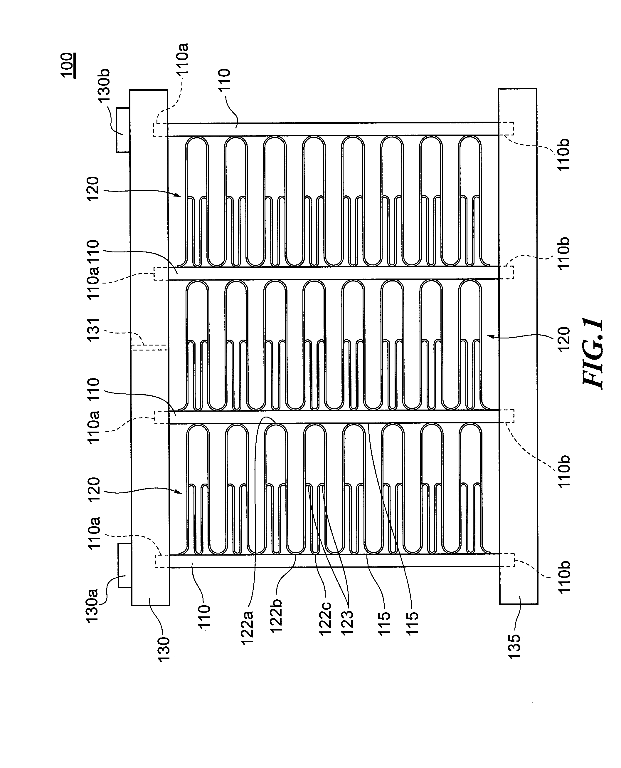
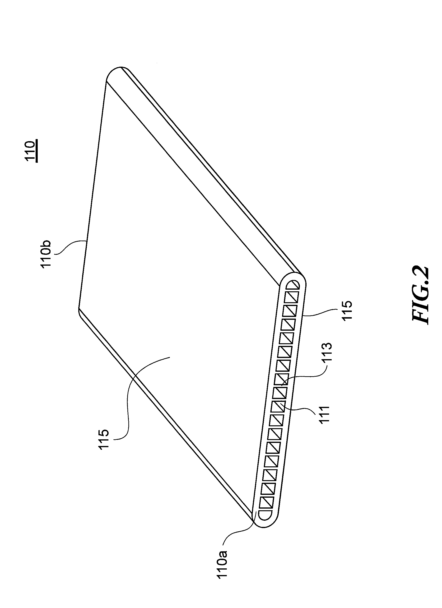
[0029]As illustrated in FIG. 1, a heat exchanger 100 includes a plurality of tubes 110 arranged in parallel to each other, through which a refrigerant flows, and fins 120 each joined by brazing between adjacent tubes 110. In the illustrated example, the plurality of tubes 110 are communicated to hollow header tanks 130 and 135 at both ends of the plurality of tubes 110 in their longitudinal direction (refrigerant flowing direction). The header tank 130 provided on the upper side includes a refrigerant entrance portion 130a provided on one end side, a refrigerant exit portion 130b provided on the other end side, and a part it ion plate 131 provided at a center thereof, for partitioning inside of the header tank 130. With this, the refrigerant flowing in from the entrance portion 130a of the header tank 130 flows through the tubes 110 (two tubes on the left side in FIG. 1) communicated on the entrance portion 130a side with respect to the partition plate 131, and flows into the header...
second embodiment
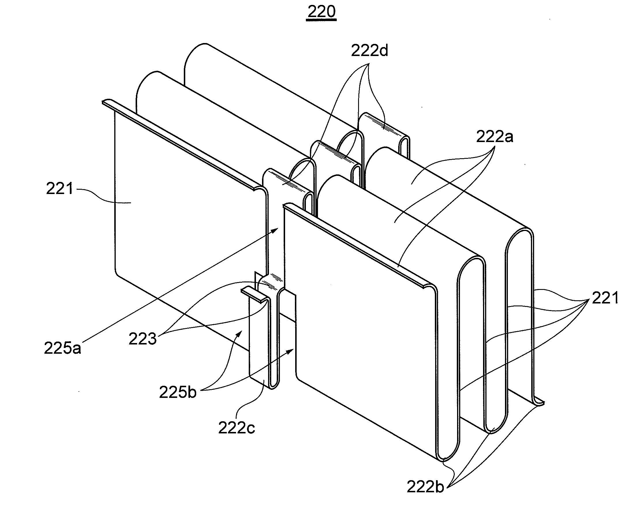
[0036]FIGS. 5 and 6 illustrate a fin 220 of a heat exchanger 200 according to a second embodiment of the present invention. Note that, the heat exchanger 200 of the second embodiment has a configuration in which the fin 220 has a structure different from that of the fin 120 of the heat exchanger 100 of the first embodiment. Therefore, description other than that of the fin 220 is omitted herein.
[0037]As illustrated in FIGS. 5 and 6, the fin 220 is a so-called corrugated fin, and includes a flat portion 221 having a flat plate shape and a bent portion 222 bent with a predetermined curvature radius, which are formed alternately in the longitudinal direction. The bent portion 222 is a part to be joined to the flat surface 115 of the tube 110, and includes a first bent portion 222a to be joined to the flat surface 115 of one of the opposing tubes 110, and a second bent portion 222b to be joined to the flat surface 115 of the other of the opposing tubes 110. In the illustrated example, t...
third embodiment
[0044]FIGS. 7 and 8 illustrate a fin 320 of a heat exchanger 300 according to a third embodiment of the present invention. Note that, the heat exchanger 300 of the third embodiment has a configuration in which the fin 320 has a structure different from that of the fin 120 of the heat exchanger 100 of the first embodiment. Therefore, description other than that of the fin 320 is omitted herein.
[0045]As illustrated in FIGS. 7 and 8, the fin 320 is a so-called corrugated fin, and includes a flat portion 321 having a flat plate shape and a bent portion 322 bent with a predetermined curvature radius, which are formed alternately in the longitudinal direction. The bent portion 322 is a part to be joined to the flat surface 115 of the tube 110, and includes a first bent portion 322a to be joined to the flat surface 115 of one of the opposing tubes 110, and a second bent portion 322b to be joined to the flat surface 115 of the other of the opposing tubes 110. In the illustrated example, the...
PUM
 Abstract
Description
Claims
Application Information