Transducer and transducer module

a technology of transducer and module, applied in the direction of piezoelectric/electrostrictive device details, magnetic circuit shape/form/construction, instruments, etc., can solve the problems of price and difficulty in assembling piezoelectric plates, and achieve the effect of enhancing haptic feedback or acoustic propagation

Inactive Publication Date: 2013-03-21
CHIEF LAND ELECTRONICS CO LTD
View PDF8 Cites 555 Cited by
  • Summary
  • Abstract
  • Description
  • Claims
  • Application Information

AI Technical Summary

Benefits of technology

[0013]A third embodiment of this invention provides a transducer module comprising at least one plate and the transducer of the first or second embodiment. Accordingly, the transducers and transducer modules provided by this invention can enhance a haptic feedback or an acoustic propagation, or adjust a resonant mode.

Problems solved by technology

However, the price and the difficulty of assembling the piezoelectric plates of an actuator are proportional to its stacked number.

Method used


Image

  • Transducer and transducer module
  • Transducer and transducer module
  • Transducer and transducer module

Examples


first embodiment

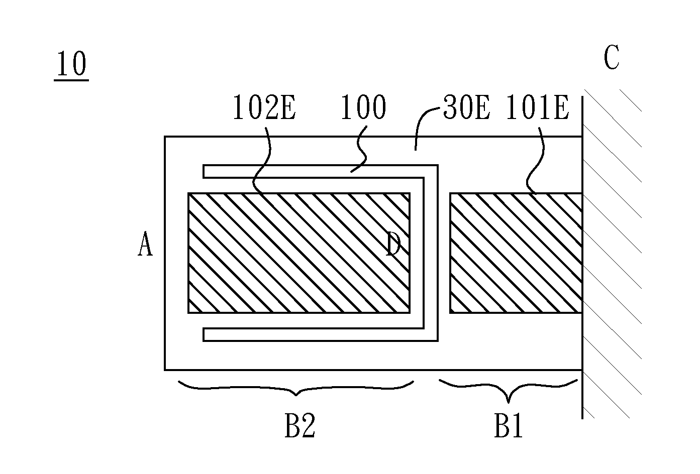
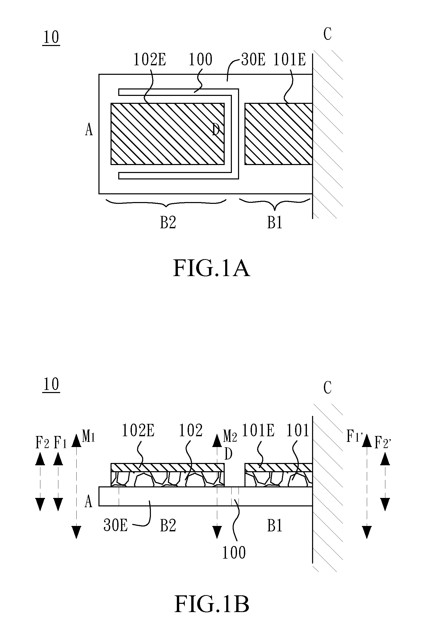
[0030]FIG. 1A and FIG. 1B show a transducer 10 according to this invention, in which FIG. 1A is a top view, and FIG. 1B is a side cross-section view. The transducer 10 of this embodiment primarily includes a conductive layer 30E having two ends, end A and end C, in which end C is used as a fixed end, and end A is used as a swing end. The conductive layer 30E further comprises a U-shaped slit 100 having an opening toward the swing end A. In addition, a first smart material layer 101 is arranged on the conductive layer 30E and between the U-shaped slit 100 and the fixed end C. A second smart material layer 102 is arranged on the conductive layer 30E and between the U-shaped slit 100 and the swing end A. A first electrode layer 101E is arranged on the first smart material layer 101. A second electrode layer 102E is arranged on the second smart material layer 102.

[0031]When electric field is applied on the conductive layer 30E, the first electrode layer 101E, and the second electrode la...

second embodiment

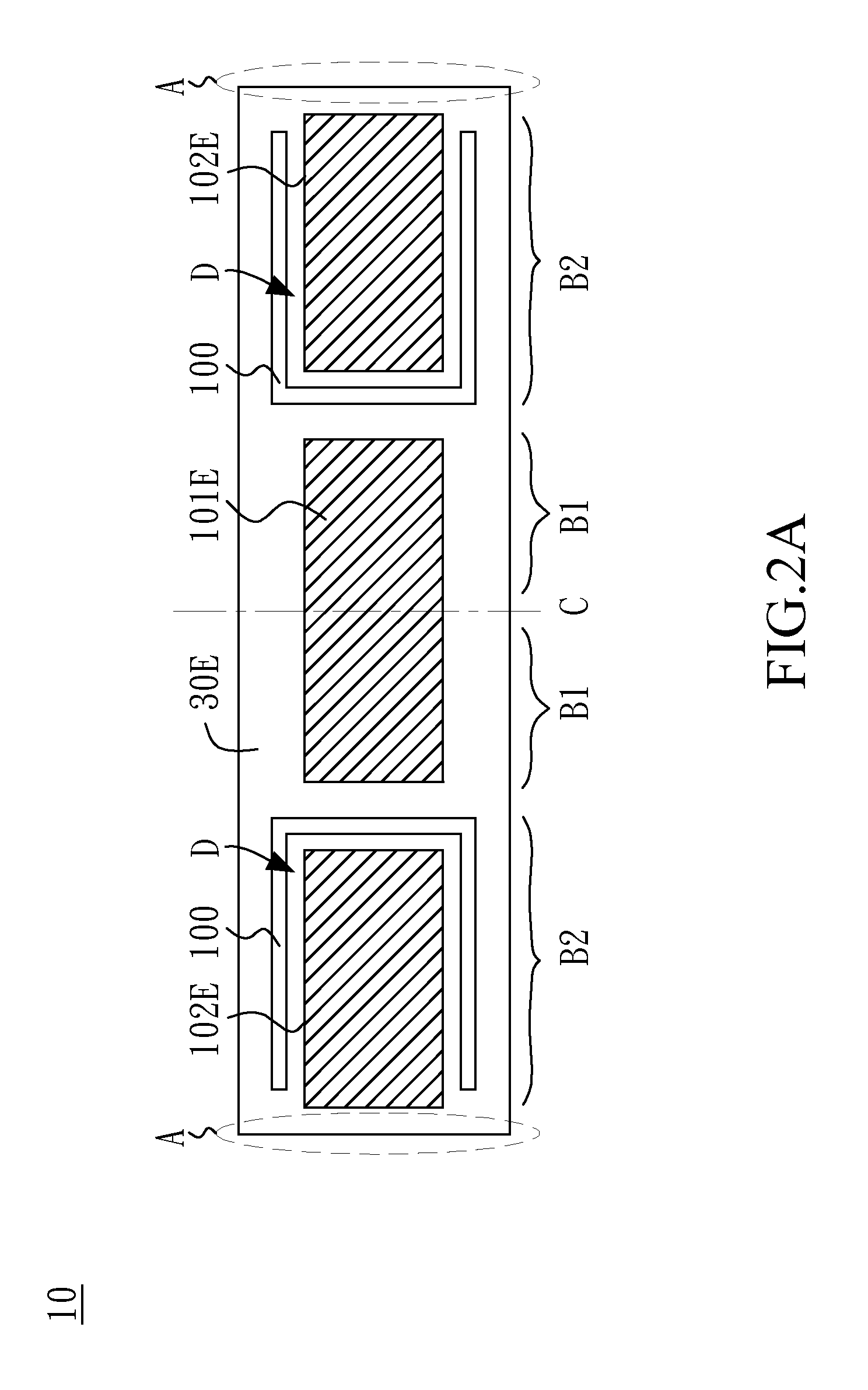
[0035]FIG. 2A and FIG. 2B show a transducer 10 according to this invention, in which FIG. 2A is a top view, and FIG. 2B is a side cross-section view. The transducer 10 of this embodiment primarily includes a conductive layer 30E having two ends used as two swing ends A and a central section used as a fixed end C. The conductive layer 30E further comprises two U-shaped slits 100, and each slit has an opening toward the swing end A arranged at the same side. In addition, a first smart material layer 101 is arranged on the conductive layer 30E and between the two U-shaped slits 100. Two second smart material layers 102 are arranged on the conductive layer 30E and between the U-shaped slit 100 and the swing end A respectively. A first electrode layer 101E is arranged on the first smart material layer 101. Two second electrode layers 102E are respectively arranged on the two second smart material layers 102.

[0036]When electric field is applied on the conductive layer 30E, the first elect...


PUM


Abstract

Transducers and transducer modules having the transducers are disclosed. An embodiment discloses a transducer that includes a conductive layer having a U-shaped slit toward its swing end. The slit is configured to enhance a haptic feedback or an acoustic propagation, or adjust a resonant mode.

Description

CROSS-REFERENCE TO RELATED APPLICATIONS[0001]The entire contents of Taiwan Patent Application No. 100133579, filed on Sep. 19, 2011, from which this application claims priority, are incorporated herein by reference.BACKGROUND OF THE INVENTION[0002]1. Field of the Invention[0003]The present invention relates to transducers and transducer modules having the transducers.[0004]2. Description of Related Art[0005]A transducer is a device that converts one type of energy to another. A motor and an electric generator are common electromechanical transducers. The motor converts electric energy to mechanical energy via electromagnetic induction. The electric generator, on the contrary, converts mechanical energy to electric energy.[0006]Moreover, the transducer may be implemented by smart materials. When a stimulus, such as stress, temperature, electricity, magnetic field, pH, humidity, and so on, is provided to a smart material, one or more properties of the smart material will be changed. T...

Claims


Application Information

Patent Timeline
Patent Type & Authority Applications(United States)
IPC IPC(8): G01H11/08H01L41/04
CPCG06F3/017H01L41/094H01L27/20H10N30/2042H02K1/16H02K1/26
Inventor CHING, CHIA-NANCHUANG, TSI-YU
Owner CHIEF LAND ELECTRONICS CO LTD
Why Eureka
Try Eureka