Recording apparatus

a recording apparatus and carriage technology, applied in the direction of printing mechanisms, power drive mechanisms, printing, etc., can solve the problems of swinging carriages, natural design to cope, low ink landing precision, etc., and achieve the effect of reducing the cost of recording apparatus

Active Publication Date: 2013-03-21
SEIKO EPSON CORP
View PDF3 Cites 11 Cited by
  • Summary
  • Abstract
  • Description
  • Claims
  • Application Information

AI Technical Summary

Benefits of technology

[0013]An advantage of some aspects of the invention is to provide a gap adjusting mechanism interposed between a carriage and a slide member and configured to slide a gap adjusting cam to adjust a PG, thereby suppressing swinging of the carriage caused by lifting of the carriage from the gap adjusting cam or lifting of the gap adjusting cam from the slide member.
[0014]To bring about the advantage, according to a first aspect of the invention, there is provided a recording apparatus including a recording head that performs recording on a medium, and a carriage movable in a scanning direction of the recording head. The carriage includes a carriage body holding the recording head, a slide member that is provided in such a way that a position of the slide member relative to the carriage body is changeable in a direction where a gap between the recording head and the medium changes, and moves together with carriage body in the scanning direction, a gap adjusting cam that is interposed between the slide member and the carriage body to receive a dead weight of the carriage, and changes in the scanning direction relative to the slide member and the carriage body to change the gap, and a restriction section that restricts at least one of expansion of the interval between the carriage body and the gap adjusting cam and expansion of the interval between the gap adjusting cam and the slide member in such a way as to keep a predetermined gap.

Problems solved by technology

This phenomenon lowers the ink landing precision.
However, only the dead weight of the carriage is applied between the carriage and the gap adjusting cam and between the gap adjusting cam and the slide member, so that the carriage may be lifted up from the gap adjusting cam or the gap adjusting cam may be lifted up from the slide member when the carriage is driven, causing swinging of the carriage.
The aforementioned recording apparatuses according to the related art do not have such a gap adjusting structure, and are not naturally designed to cope with the aforementioned technical problem.

Method used


Image

  • Recording apparatus
  • Recording apparatus
  • Recording apparatus

Examples


Embodiment Construction

[0040]An exemplary embodiment of the invention will be described hereinbelow with reference to the accompanying drawings. However, the invention is not limited to the embodiment described below, and may be modified in various forms within the scope of the invention specified in the appended claims. The following description of the embodiment is given on the premise that those modifications are encompassed in the scope of the invention.

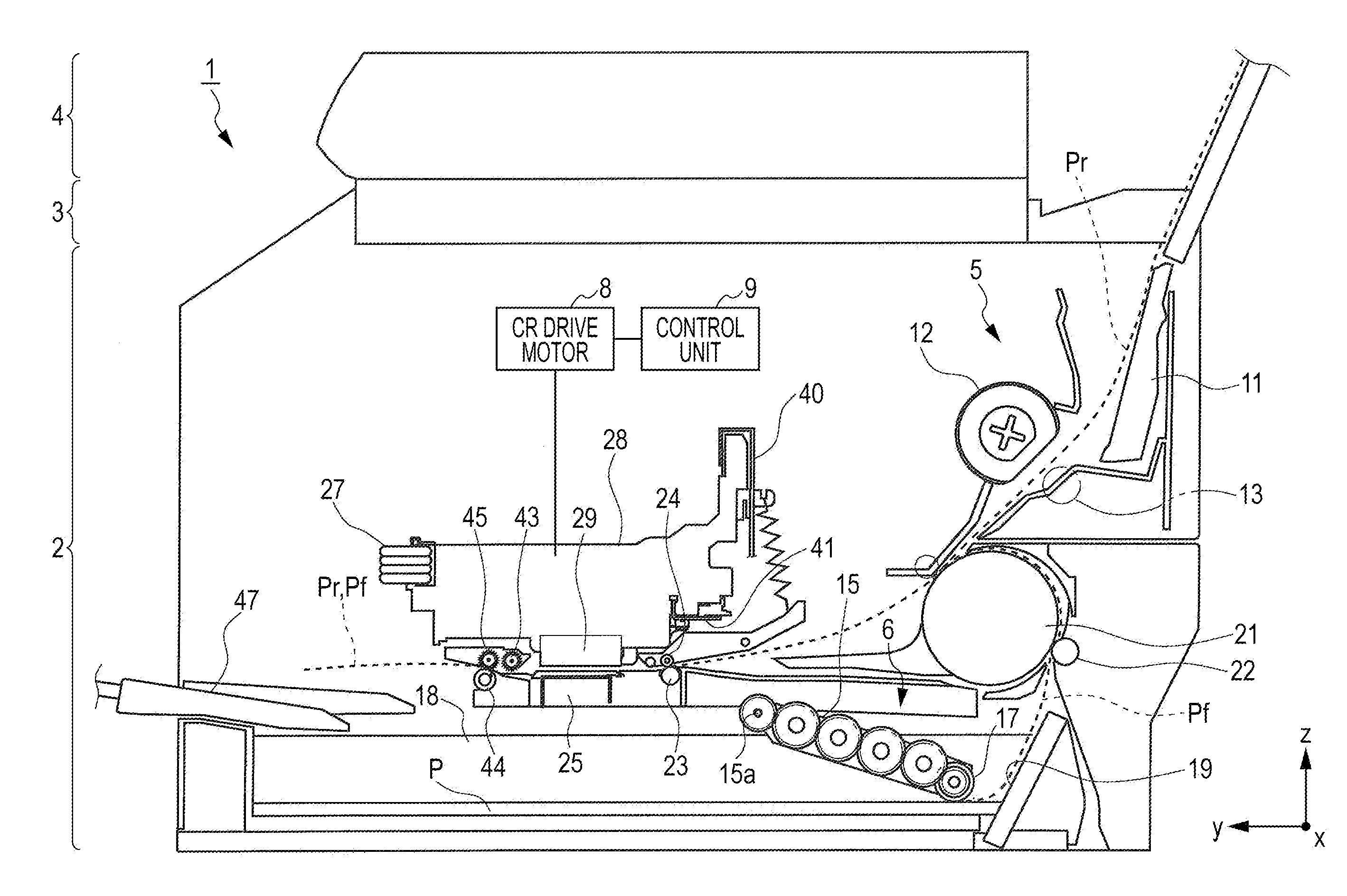
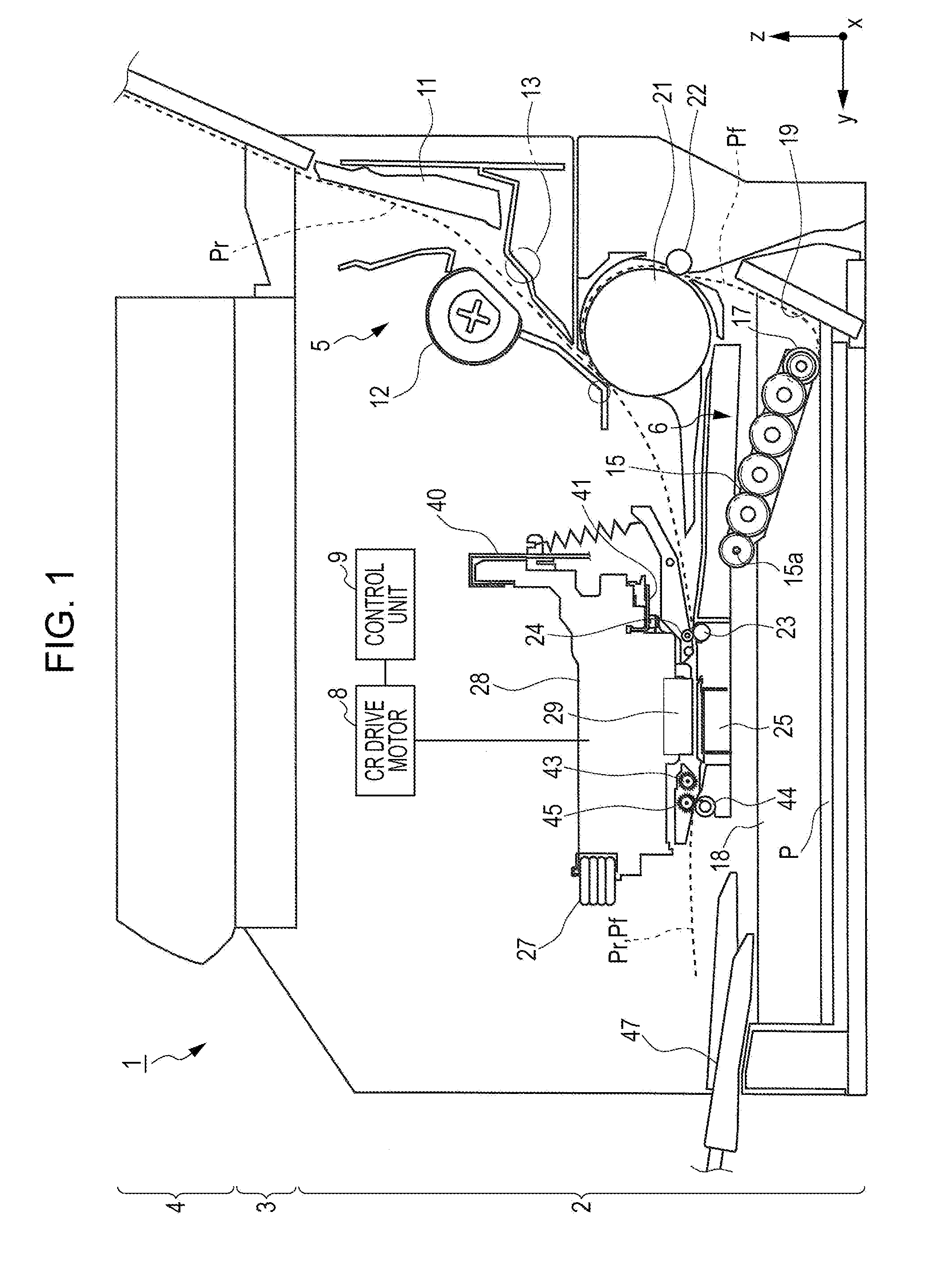
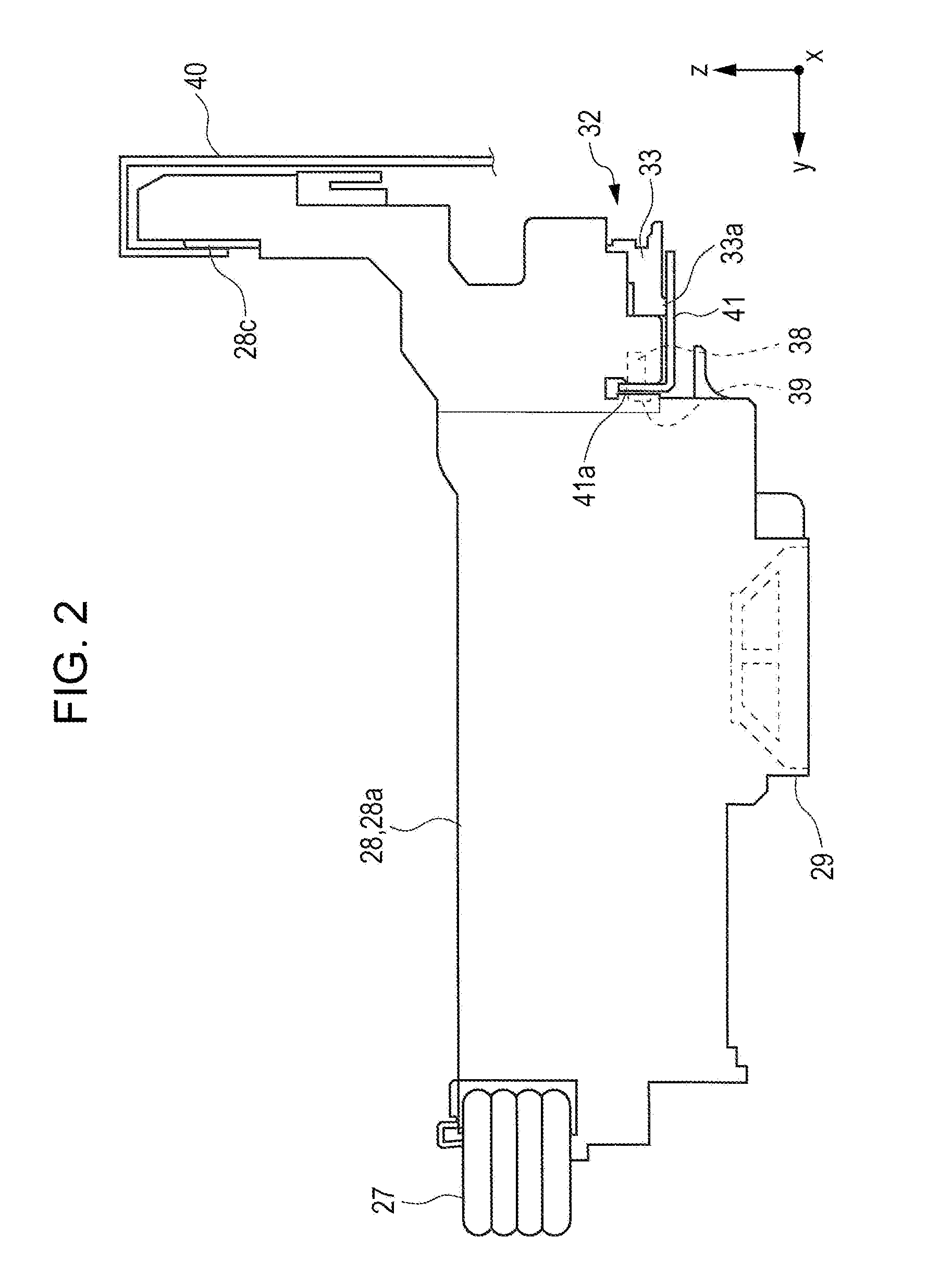
[0041]FIG. 1 is a side cross-sectional view of an ink jet printer 1 according to the exemplary embodiment of the invention. FIG. 2 is a side view of a carriage 28, and FIG. 3 is a perspective view showing the carriage 28 form the lower rear side. FIG. 4 is an exploded perspective view of a gap adjusting section 32, FIG. 5 is a cross-sectional view of the gap adjusting section 32, and FIG. 6 is a perspective view of the gap adjusting section 32. FIG. 7 is a perspective view of a plate spring (urging section) 37, and FIG. 8 is a diagram illustrating how ...


PUM


Abstract

A recording apparatus includes a recording head and a carriage. The carriage includes a slide member that is provided so that the position of the slide member relative to a carriage body is changeable in a direction where a gap between the recording head and a medium changes, and moves together with carriage body in the scanning direction, a gap adjusting cam that is interposed between the slide member and the carriage body, and, upon reception of the dead weight of the carriage, changes in the scanning direction relative to the slide member and the carriage body to change the gap, and a restriction section that restricts at least one of expansion of the interval between the carriage body and the gap adjusting cam and expansion of the interval between the gap adjusting cam and the slide member in such a way as to keep a predetermined gap.

Description

BACKGROUND[0001]1. Technical Field[0002]The present invention relates to a recording apparatus that performs recording on a medium.[0003]2. Related Art[0004]An ink jet printer as one example of a recording apparatus will be described hereinbelow by way of example. The ink jet printer includes a recording head mounted on a carriage to eject ink on a recording sheet or paper.[0005]The carriage is configured such that the carriage is guided by a guide member extending in the scanning direction of the recording head (hereinafter referred to as “main scanning direction”), and is fixed to a part of, for example, an endless belt, whereby the traction of the endless belt causes the carriage to reciprocate in the main scanning direction.[0006]Because the position of the carriage at which the endless belt is fixed cannot normally coincide with the position of the center of gravity of the carriage, the phenomenon that the carriage tends to rotate (called “swinging phenomenon”) may occur when t...

Claims


Application Information

Patent Timeline
Patent Type & Authority Applications(United States)
IPC IPC(8): B41J23/02
CPCB41J25/308
Inventor OHASHI, KAZUYOSHIKISHIGAMI, MINORUTANAKA, DAISUKEMIZUNO, SHOTA
Owner SEIKO EPSON CORP
Why Eureka
Try Eureka