Optical fiber adapter with shutter member

a technology of optical fiber and shutter member, which is applied in the field of optical fiber adapters, can solve the problems of affecting the life of people, affecting the effect of the shutter member, and the cap b>180/b> being prone to get los

Active Publication Date: 2013-03-21
PROTAI PHOTONIC +1
View PDF4 Cites 16 Cited by
  • Summary
  • Abstract
  • Description
  • Claims
  • Application Information

AI Technical Summary

Benefits of technology

[0013]The present disclosure provides a shutter member for an optical fiber adapter that may obstruct the light beams emitted from the accommodation room thereby preventing the eyes from exposure to the light beams.

Problems solved by technology

However, the high power laser beam used to carry information is usually invisible.
If the emitted light beam is high power and not obstructed, a lasting exposure to such light beam is harmful to people, particularly to the eyes.
However, the cap 180 is apt to get lost and it is still possible to expose the eyes to the light beam during mating.
As a result, the user has no chance to expose to the high-power light beam.
However, the construction of the adapter 200 is much more complex than that of the adapter 100.
However, the structure of the protection cap 300 is somewhat complex and therefore it is not inexpensive.
The introduction of the protection cap 300 to obstruct the light beam will cost much.

Method used


Image

  • Optical fiber adapter with shutter member
  • Optical fiber adapter with shutter member
  • Optical fiber adapter with shutter member

Examples


first embodiment

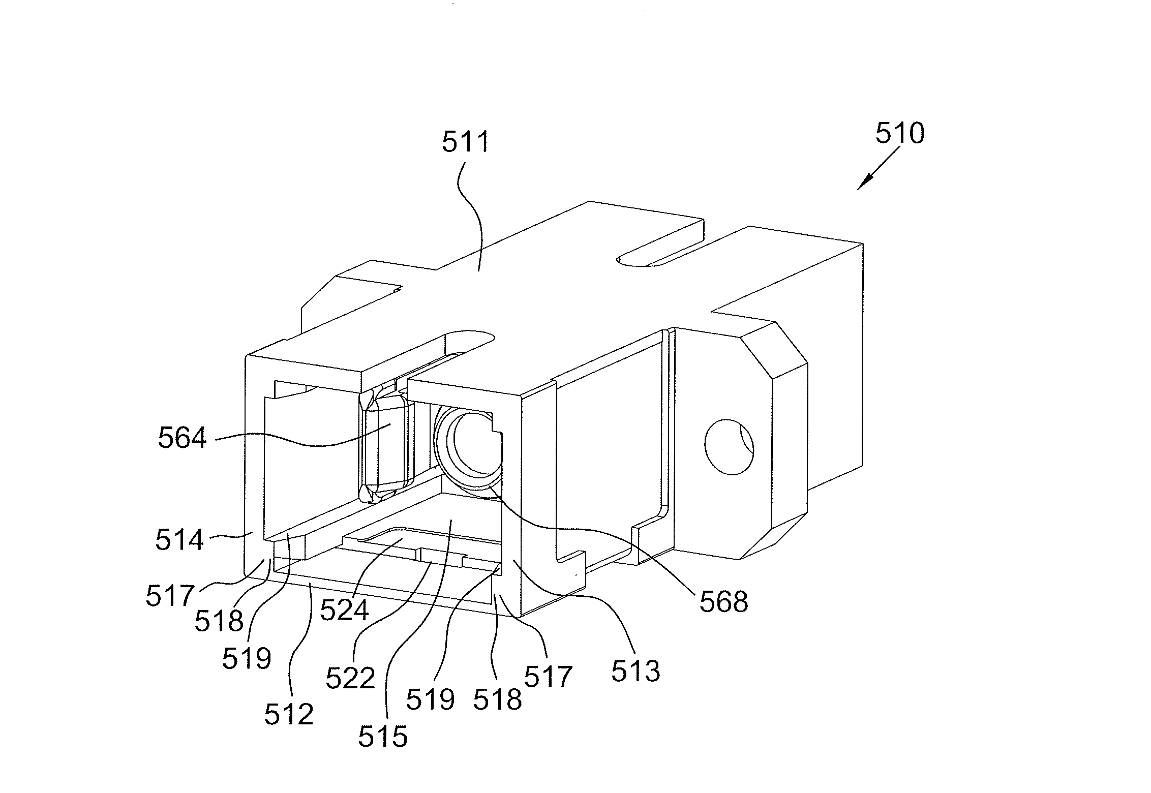
[0040]Referring to FIGS. 5a, 5b and 6, the optical fiber adapter according to the present disclosure includes a molded plastic main body 510 and an elastic shutter member 570. The main body 510 is substantially rectangular and has an accommodation room 515 defined by a top side-wall 511, a bottom side-wall512, a right side-wall 513 and a left side-wall 514. An inner housing 560, such as a hooking member, is placed within the accommodation room 515. The hooking member 560 is provided with a pair of hooks 564 extending from one end of a generally rectangular flange 562. The flange 562 includes a hollow cylinder 568 located between the two hooks 564. A pair of protrusions 517 substantially has an inverted L shape and is formed within the accommodation room 515 and on the bottom side-wall 512. Each of the protrusions 517 includes a vertical portion 518 extending upward from the bottom side-wall 512 and a horizontal portion 519 extending horizontally from the top of the vertical portion ...

second embodiment

[0048]Referring to FIGS. 12 and 13, the optical fiber adapter according to the present disclosure includes a molded plastic main body 710 and an elastic shutter member 770. The main body 710 has an accommodation room defined by a top side-wall 711, a bottom side-wall 712, a right side-wall 713 and a left side-wall 714. The accommodation room is divided into two halves by a compartment wall 715 that is parallel to the right side-wall 713 and left side-wall 714 and connects with the top side-wall 711 and bottom side-wall 712. The half of the accommodation room defined by the top side-wall 711, bottom side-wall 712, compartment wall 715 and right side-wall 713 is named as the right accommodation room 726 and the other half of the accommodation room defined by the top side-wall 711, bottom side-wall 712, compartment wall 715 and left side-wall 714 is named as the left accommodation room 728. Each of the right and left accommodation rooms 726, 728 has an opening 708. A pair of indentatio...


PUM


Abstract

An optical fiber adapter according to the present disclosure includes a main body and an elastic shutter member. The main body has an accommodation room defined by a first wall, a second wall, a third wall and a fourth wall, wherein the first wall faces the third wall and connects with the second and fourth walls. An indentation is formed within the accommodation room and on the third wall. The shutter member includes two fixing portions positioned within the accommodation room and on the third wall, a shutter plate, a connecting portion connecting the fixing portions with the shutter plate, and a hooking portion positioned within the accommodation room. The hooking portion extends from the connecting portion to hook on to the indentation on the third wall, and the shutter plate extends from the connecting portion and into the accommodation room.

Description

CROSS REFERENCE TO RELATED APPLICATION[0001]This application claims the priority benefit of China Patent Application Serial Number 201110281073.9 filed Sep. 21, 2011, the full disclosure of which is incorporated herein by reference.BACKGROUND OF THE INVENTION[0002]1. Field of the Invention[0003]The present invention relates to an optical fiber adapter, and more particularly, to an optical fiber adapter with a shutter member.[0004]2. Description of the Related Art[0005]Recently, the optical fiber has been widely used as signal transmission media because of its high bandwidth and low loss nature. In order to transmit over a longer distance without the need of repeaters, it is common to use a high power diode laser to launch a laser beam into the optical fiber. However, the high power laser beam used to carry information is usually invisible. In other words, the human eyes will be unable to sense the high power laser beam if it leaves from the open end of a fiber cable. Thus, it is req...

Claims


Application Information

Patent Timeline
Patent Type & Authority Applications(United States)
IPC IPC(8): G02B6/38
CPCG02B6/3849G02B6/3825
Inventor LIN, I EN
Owner PROTAI PHOTONIC
Why Eureka
Try Eureka