Optical fiber adapter with shutter member

a technology of optical fiber and shutter member, which is applied in the field of optical fiber adapters, can solve the problems of affecting the life of people, affecting the effect of the shutter member, and the cap b>180/b> being prone to get los

Active Publication Date: 2013-04-04
EZONTEK TECH
View PDF13 Cites 23 Cited by
  • Summary
  • Abstract
  • Description
  • Claims
  • Application Information

AI Technical Summary

Benefits of technology

[0013]The present disclosure provides a shutter member for an optical fiber adapter that may obstruct the light beams emitted from the accommodation room thereby preventing the eyes from exposure to the light beams.

Problems solved by technology

However, the high power laser beam used to carry information is usually invisible.
If the emitted light beam is high power and not obstructed, a lasting exposure to such light beam is harmful to people, particularly to the eyes.
However, the cap 180 is apt to get lost and it is still possible to expose the eyes to the light beam during mating.
As a result, the user has no chance to expose to the high-power light beam.
However, the construction of the adapter 200 is much more complex than that of the adapter 100.
However, the structure of the protection cap 300 is somewhat complex and therefore it is not inexpensive.
The introduction of the protection cap 300 to obstruct the light beam will cost much.

Method used


Image

  • Optical fiber adapter with shutter member
  • Optical fiber adapter with shutter member
  • Optical fiber adapter with shutter member

Examples


Embodiment Construction

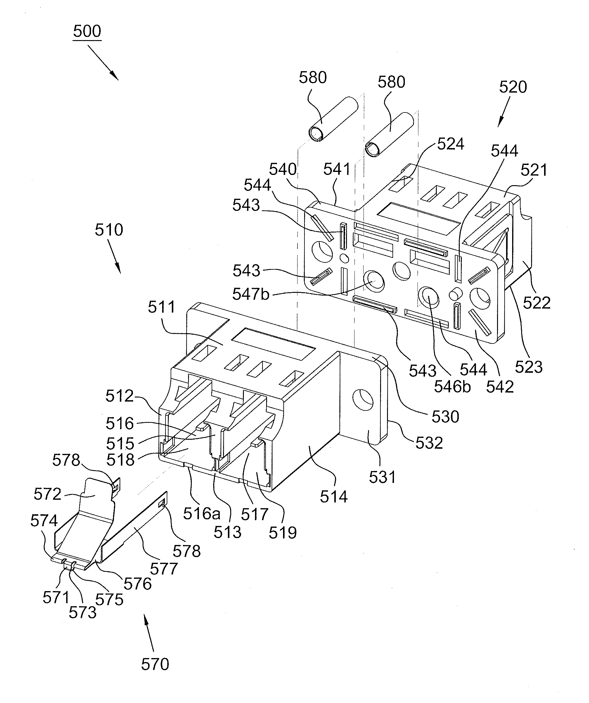
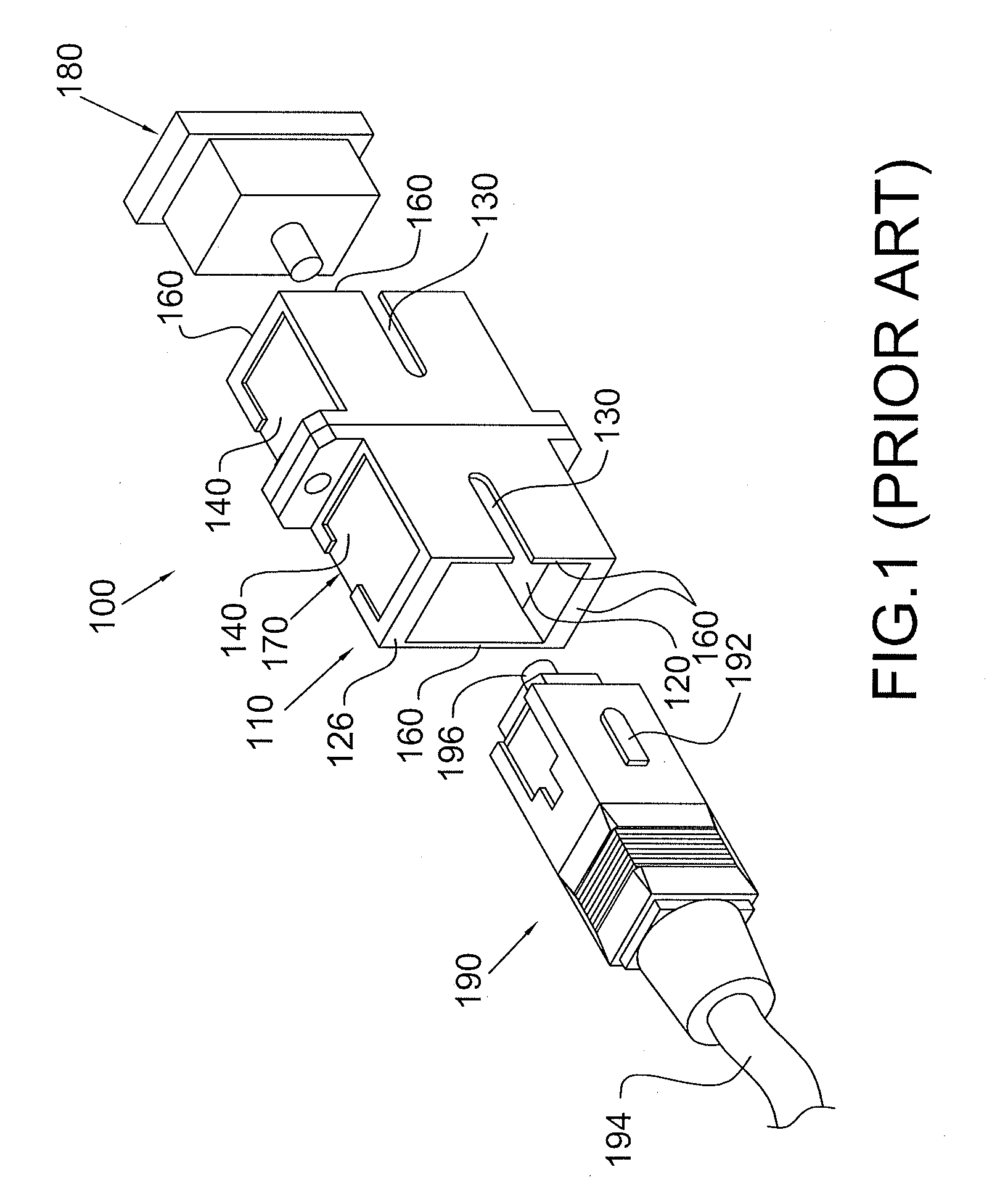
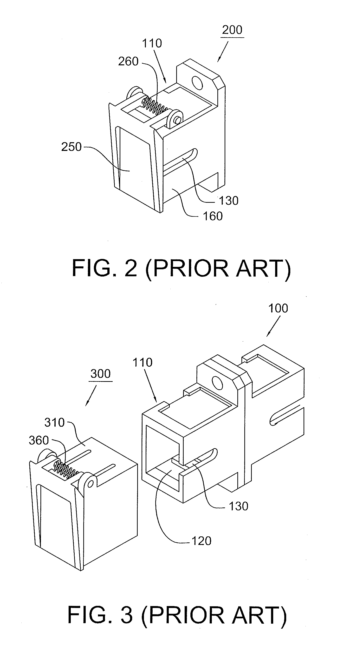
[0035]Referring to FIG. 4, a conventional LC type optical fiber connector 400 has a generally rectangular shape with a square cross section. The connector 400 includes a rectangular hollow housing 410 comprised of a top side-wall 411, a bottom side-wall 412, a right side-wall 413 and a left side-wall 414, wherein the right side-wall 413 is opposite to the left side-wall 414 and connects with the bottom side-wall 412 and the top side-wall 411. A latch 420 is molded into the top side-wall 411 and includes a living hinge 425 which allows the tab 426 to be moved up and down in a direction perpendicular to the central axis 450-450 of the connector 400. The latch 420 also includes a pair of protrusions 421 that are positioned on opposing sides of the tab 426. In addition, a ferrule 440 protrudes from a circular opening 416 on the front end of the housing 410. A spring is located inside the housing 410 to allow the ferrule 440 to move back and forth through the opening 416 (not shown in th...


PUM


Abstract

An optical fiber adapter includes a first housing and an elastic shutter member. The first housing includes a flange and an accommodation room with an opening. A hollow cylinder extends from the front surface of the flange and is positioned within the accommodation room. The shutter member includes a horizontal portion, two vertical portions, two hooks, a shutter plate and a connecting portion. The horizontal portion is positioned within the accommodation room. The two vertical portions extend from two opposing sides of the horizontal portion, respectively, and go through the openings on the flange, respectively. The two hooks extend from the two vertical portions, respectively, and are configured to hook on to the flange. The connecting portion connects the horizontal portion with the shutter plate. The shutter plate extends from the connecting portion and into the accommodation room to arrive in front of an opening of the hollow cylinder.

Description

CROSS REFERENCE TO RELATED APPLICATION[0001]This application claims the priority benefit of Taiwan Patent Application Serial Number 100135435 filed Sep. 30, 2011, the full disclosure of which is incorporated herein by reference.BACKGROUND OF THE INVENTION[0002]1. Field of the Invention[0003]The present invention relates to an optical fiber adapter, and more particularly, to an optical fiber adapter with a shutter member.[0004]2. Description of the Related Art[0005]Recently, the optical fiber has been widely used as signal transmission media because of its high bandwidth and low loss nature. In order to transmit over a longer distance without the need of repeaters, it is common to use a high power diode laser to launch a laser beam into the optical fiber. However, the high power laser beam used to carry information is usually invisible. In other words, the human eyes will be unable to sense the high power laser beam if it leaves from the open end of a fiber cable. Thus, it is require...

Claims


Application Information

Patent Timeline
Patent Type & Authority Applications(United States)
IPC IPC(8): G02B6/38
CPCG02B6/3825G02B2006/4297G02B6/3849
Inventor LIN, SUNG ANLIN, SUNG CHI
Owner EZONTEK TECH
Why Eureka
Try Eureka