Fixing Device

Active Publication Date: 2013-03-21
BROTHER KOGYO KK
View PDF13 Cites 16 Cited by
  • Summary
  • Abstract
  • Description
  • Claims
  • Application Information

AI Technical Summary

Benefits of technology

The patent text describes a fixing device that can improve the sliding performance of a fusing belt with respect to a nip plate when the nip plate is formed by rolling. This is achieved by using roll marks that extend along the conveying direction of the recording sheet, which helps to prevent excessive lubricant from being held by the nip plate and ultimately improves the quality of the fused image.

Problems solved by technology

If the nip plate is arranged such that the roll marks are orthogonal to a sheet conveying direction, sliding resistance of the fusing belt with respect to the nip plate increases and the fusing belt may not properly rotate.
In this case, however, the lubricant is excessively held by the roll marks that are orthogonal to the conveying direction.

Method used


Image

  • Fixing Device
  • Fixing Device
  • Fixing Device

Examples


Embodiment Construction

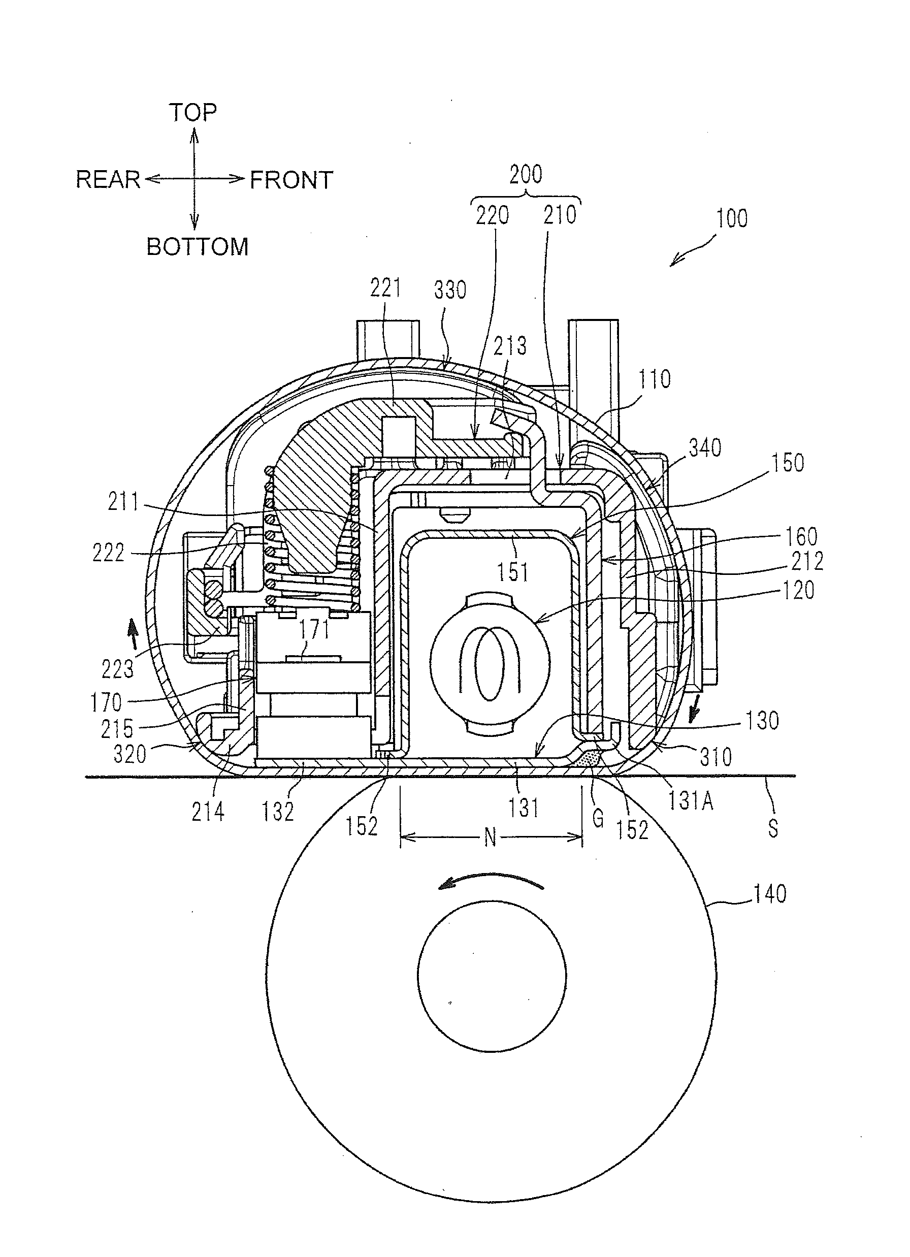
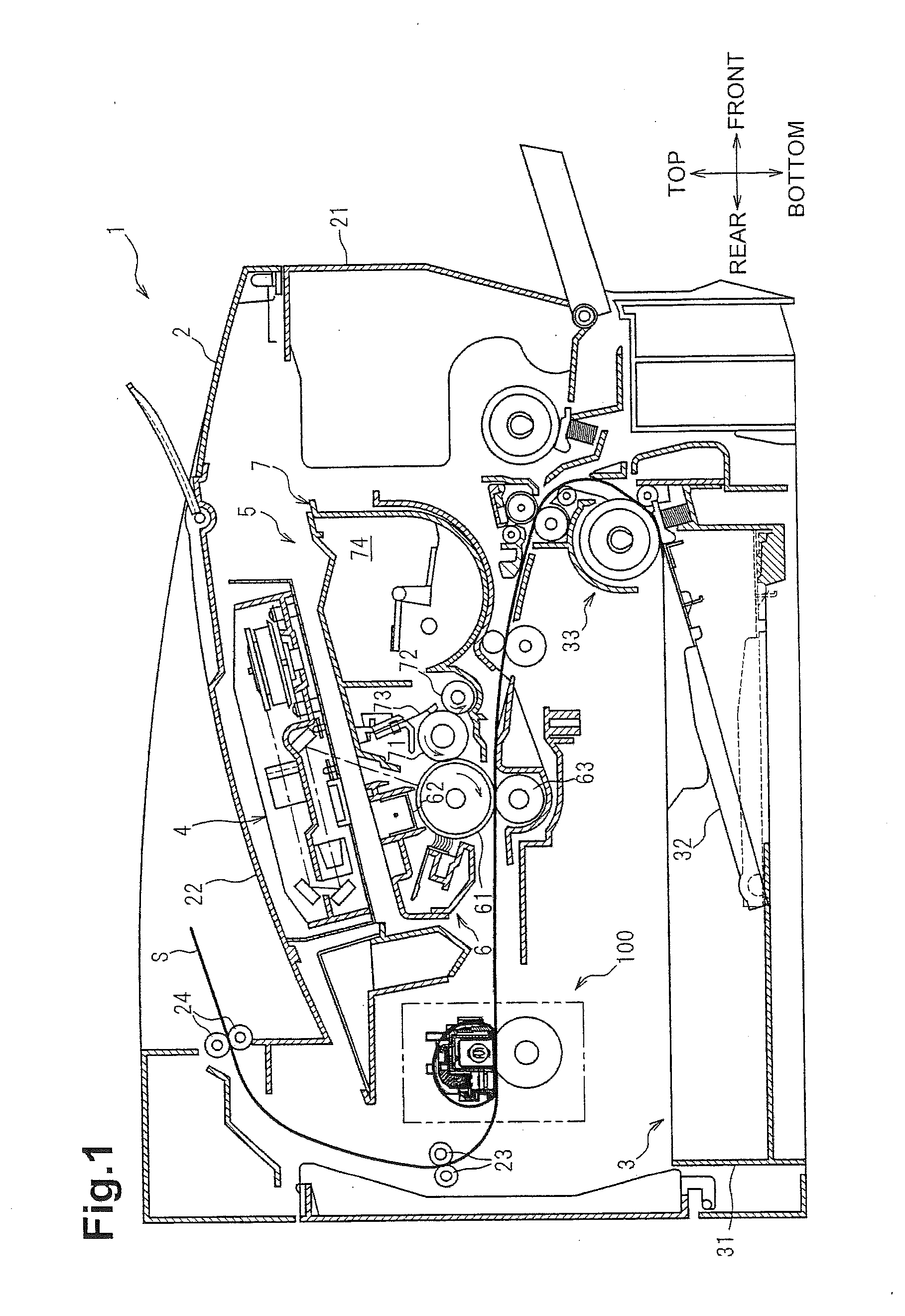
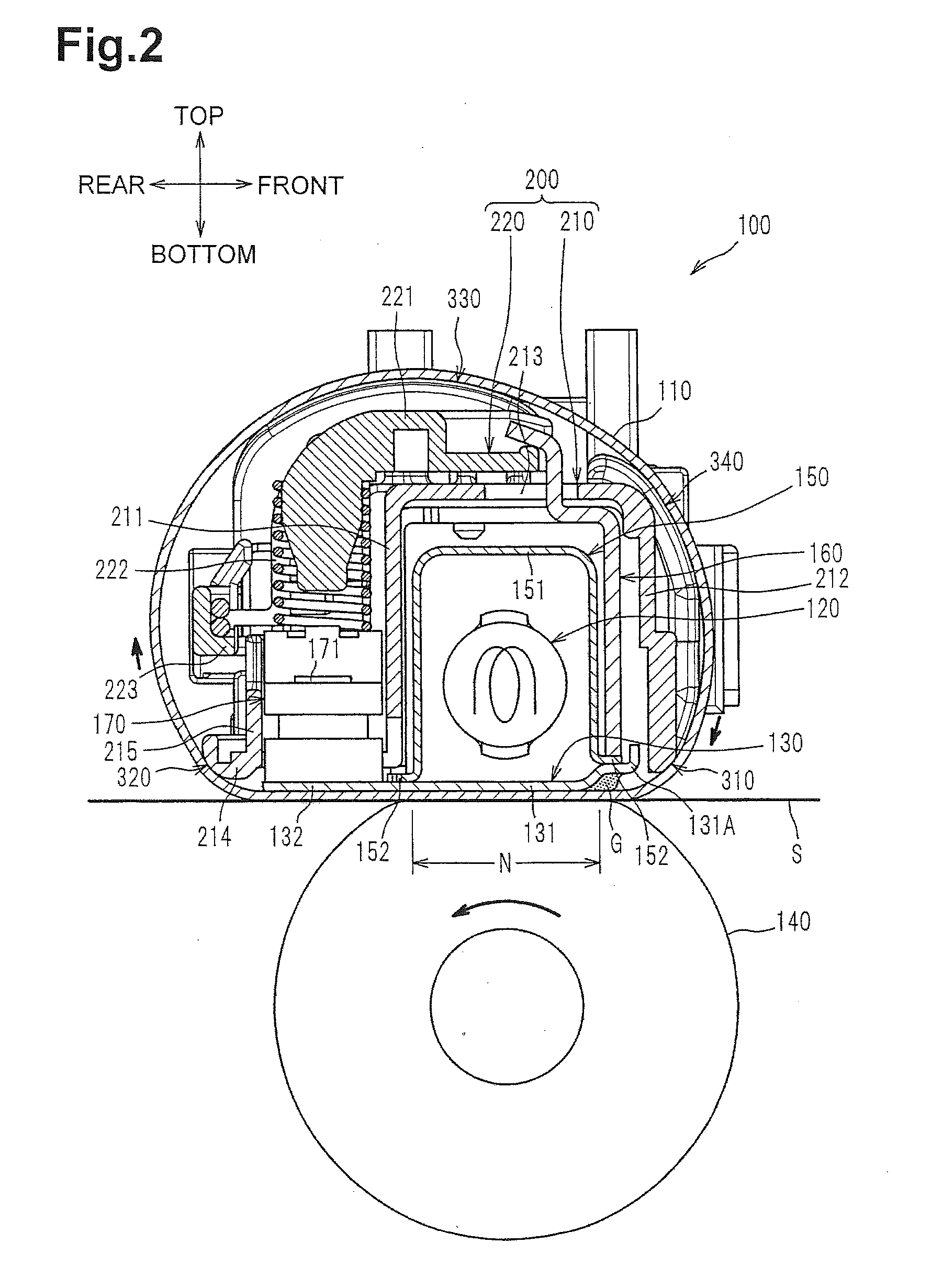
[0019]An embodiment of the present invention is described below in detail with reference to the figures. The general configuration of a laser printer 1 (an image forming apparatus) including a fixing device 100 according to an embodiment of the invention is briefly described and then the detailed configuration of the fixing device 100 is described.

[0020]The following description applies directions with reference to a user of the laser printer 1. In particular, it is assumed that the right side in FIG. 1 is “front,” the left side is “rear,” the near side is “left,” and the deep side is “right.” Also, it is assumed that the up-down direction in FIG. 1 is “up and down.”

[0021]General Configuration of Laser Printer

[0022]As shown in FIG. 1, the laser printer 1 mainly includes a feed portion 3 that feeds a sheet S as an example of a recording sheet, an exposure device 4, a process cartridge 5 that transfers a toner image (a developer image) on the sheet S, and the fixing device 100 that th...


PUM


Abstract

A fixing device includes, a belt, and a plate. The belt has a first surface and a second surface opposite to the first surface. The plate is made of metal and has a sliding surface that is configured to slide on the first surface of the belt in a predetermined direction. The sliding surface of the plate has roll marks that extend along the predetermined direction.

Description

CROSS-REFERENCE TO RELATED APPLICATION[0001]This application claims priority to JP2011-205131, filed Sep. 20, 2011, whose contents are expressly incorporated herein by reference.BACKGROUND[0002]1. Technical Field[0003]The present invention relates to a fixing device including a plate-like nip plate.[0004]2. Description of the Related Art[0005]There is known a fixing device including an infrared heater, a nip plate that is heated by the infrared heater, a cylindrical fusing belt, and a pressure roller that pinches the fusing belt between the pressure roller and the nip plate. In this fixing device, the fusing belt rotates by rotation of the pressure roller. A toner image on a sheet is thermally fixed to the sheet when the sheet is conveyed between the pressure roller and the fusing belt. In recent years, the nip plate is formed by rolling with a pair of reduction rolls. In this case, very small protrusions and depressions of the reduction rolls are transferred on surfaces of the nip ...

Claims


Application Information

Patent Timeline
IPC IPC(8): G03G15/20
CPCG03G2215/2035G03G15/2053
Inventor SUZUKI, NOBORUISHIDA, KEIMATSUNO, TAKUJIMIYAUCHI, YOSHIHIRO
Owner BROTHER KOGYO KK
Why Eureka
Try Eureka