Fuel injector

a fuel injector and injector technology, applied in the direction of fuel injection apparatus, fuel feed system, wear-reducing fuel injection, etc., can solve the problem of inability to ensure a sufficient fuel path area, achieve the effect of preventing a reduction of the flow channel area, reducing adhesion, and improving magnetic responsiveness

Inactive Publication Date: 2013-03-28
HITACHI AUTOMOTIVE SYST LTD
View PDF3 Cites 12 Cited by
  • Summary
  • Abstract
  • Description
  • Claims
  • Application Information

AI Technical Summary

Benefits of technology

[0018]It is an object of the present invention to provide an anchor shape that can ensure a sufficient fuel path area while preventing adhesion by making the adherence phenomenon rarely occur between an end face of an anchor and an end face of a fixed core even when the shapes of the fixed core and the anchor are optimized in such a way as to make a magnetic flux more responsive to make a seat valve of a fuel injector more responsive.
[0020]Even when the shapes of the fixed core and the anchor projection collision face are optimized to improve magnetic responsiveness, it is possible to dispose a fuel path in a position closer to the center of the anchor and prevent a reduction of a flow channel area. Moreover, even when a collision face between the anchor and the fixed core is located in a position closer to the outer periphery of the anchor, it is possible to divide the collision face, reduce the adhesion between the fixed core and the anchor, and reduce the valve closing delay time. This makes it possible to improve injection fuel mass accuracy.

Problems solved by technology

However, at the time of valve opening and closing of the fuel injector, response delays due to the action of a magnetic flux or fluid cause valve opening and closing operation to be completed at a time point later than a time point at which the fuel injection control apparatus actually desires to open and close the valve.
In such a case, the openings of the through holes on the side where the fixed core is located are closed with the fixed core, making it impossible to ensure a sufficient fuel path area.

Method used


Image

  • Fuel injector
  • Fuel injector
  • Fuel injector

Examples


Embodiment Construction

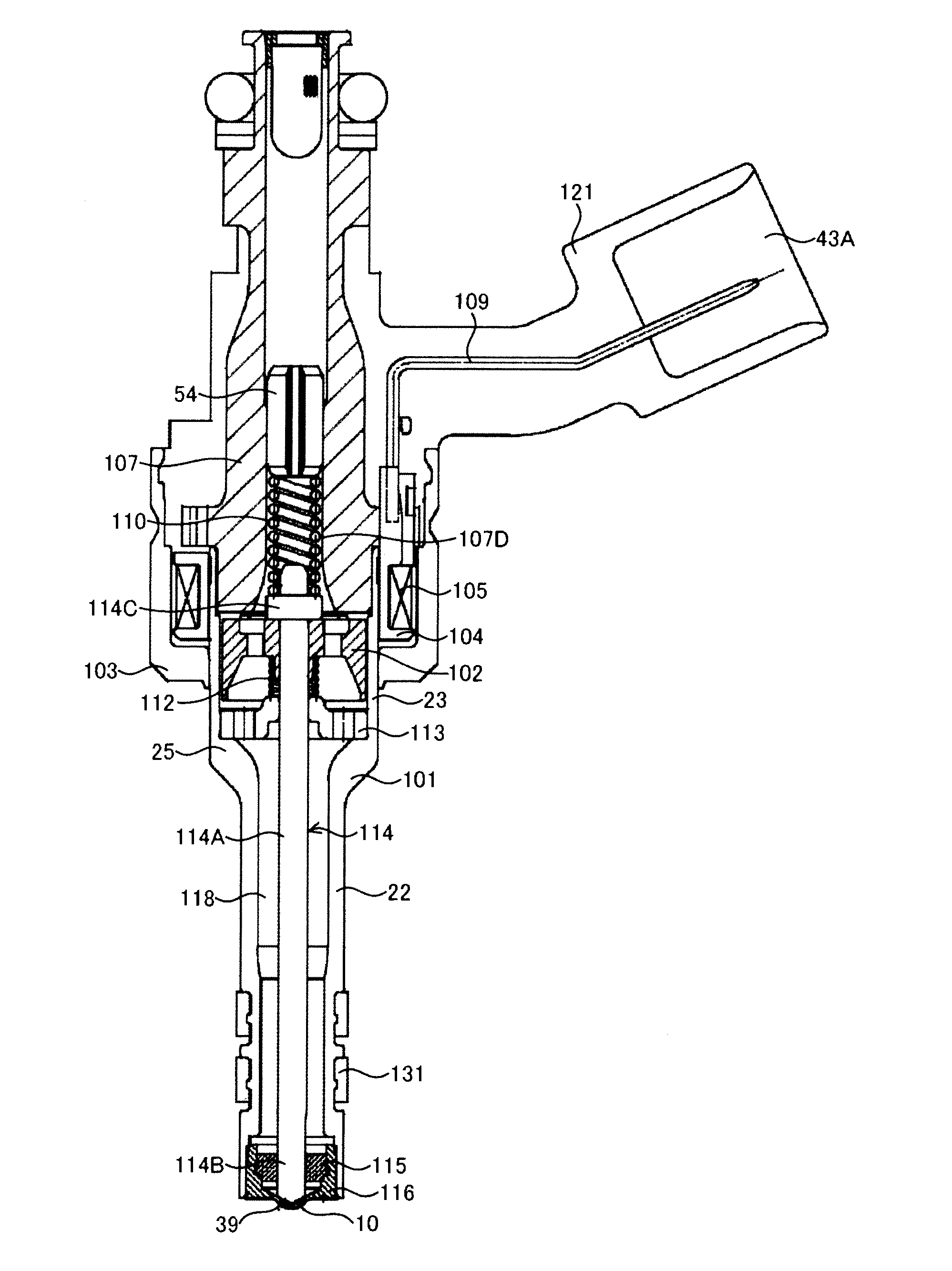
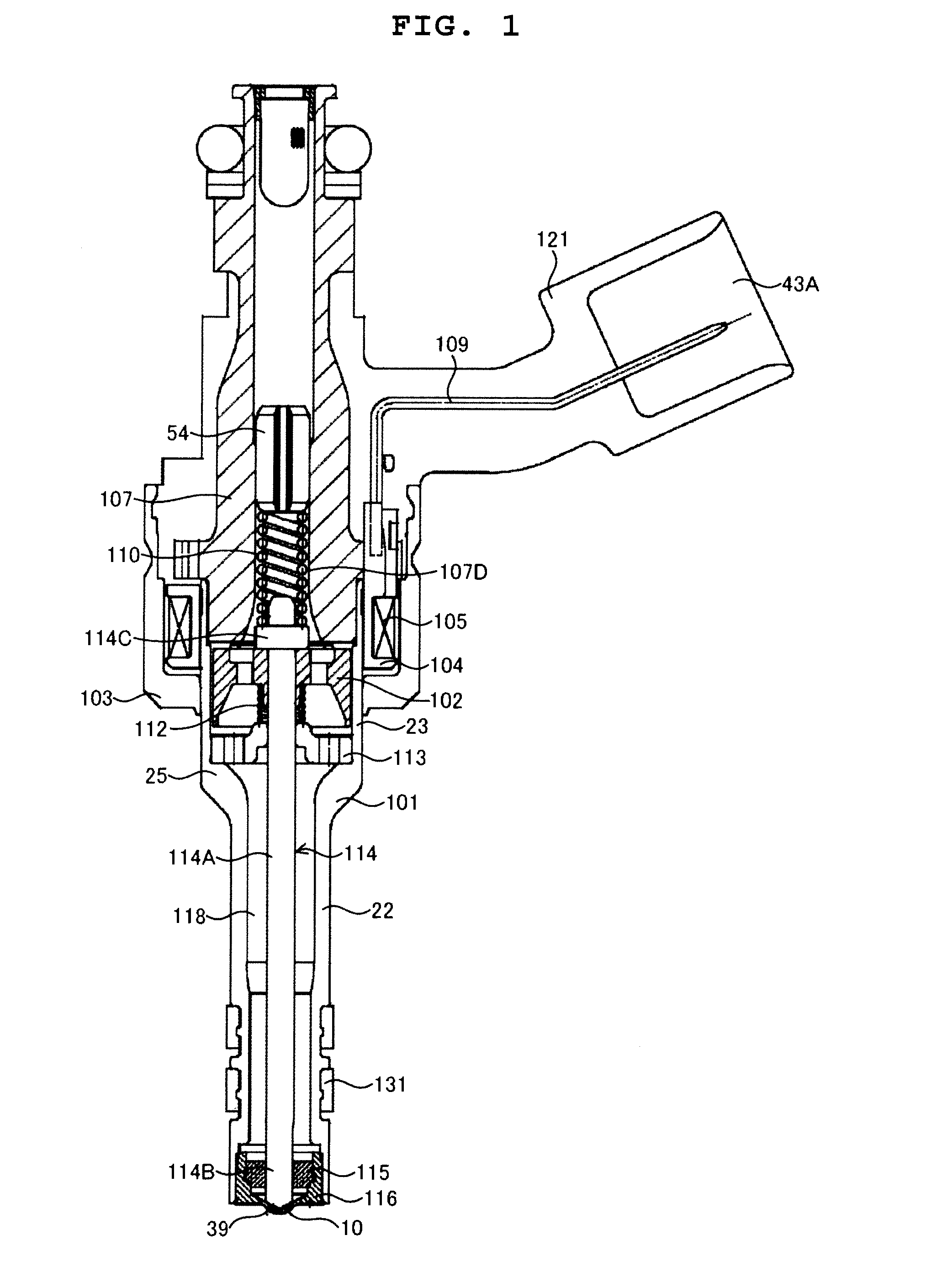
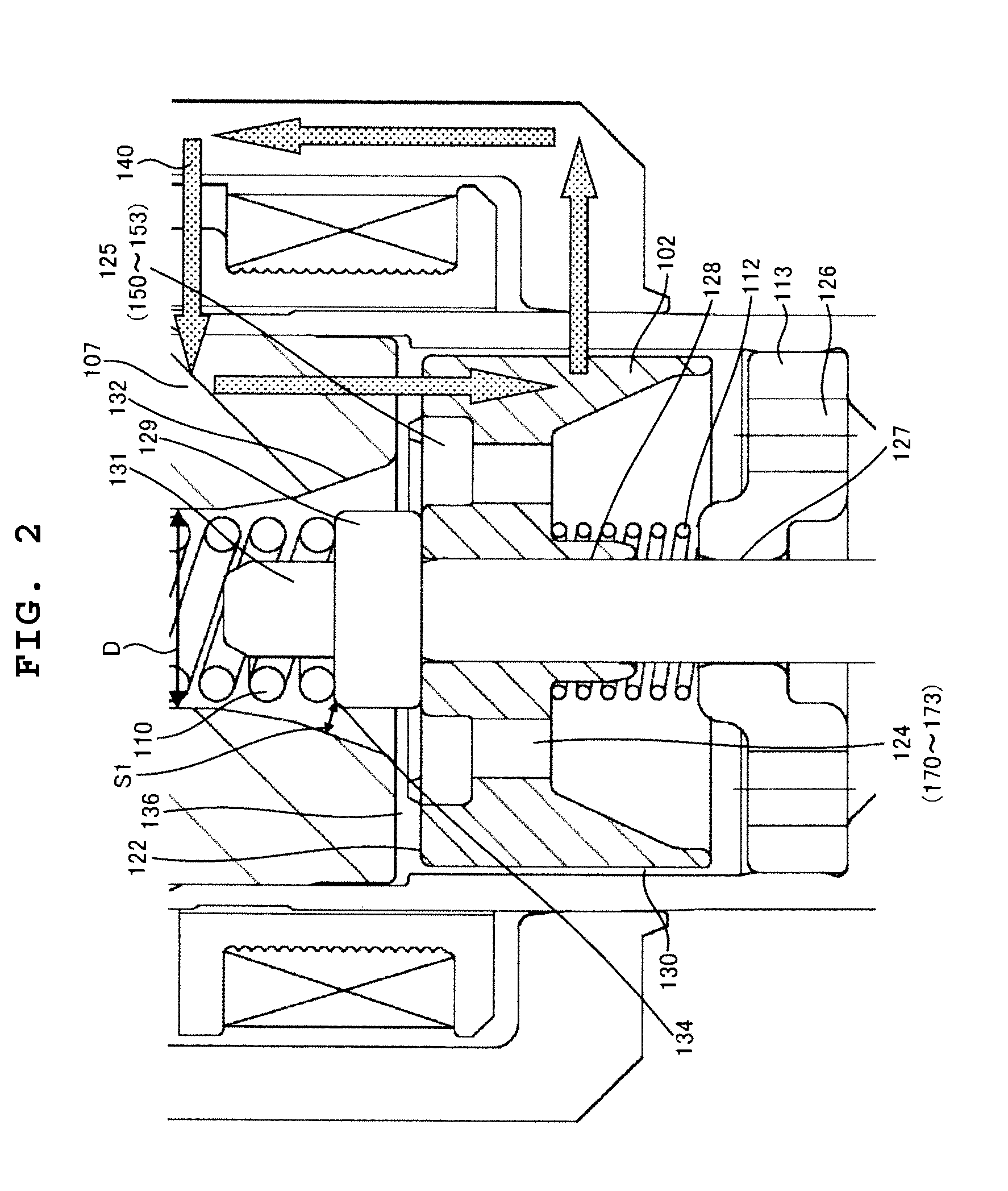
[0028]Hereinafter, the structure of an embodiment of a fuel injector according to the invention will be described by using FIGS. 1 to 7. FIG. 1 is a longitudinal sectional view of a fuel injector in this embodiment. FIG. 2 is a partially enlarged view of FIG. 1 and shows the details of the fuel injector in this embodiment.

[0029]A nozzle holder 101 includes a small-diameter cylindrical portion 22 with a small diameter and a large-diameter cylindrical portion 23 with a large diameter.

[0030]Inside a tip portion of the small-diameter cylindrical portion 22, an orifice cup 116 including a guide member 115 and a fuel orifice 10, which are stacked in this order, is inserted and is welded and fixed to the small-diameter cylindrical portion 22 along a circumference of a tip-end face of the orifice cup 116. The guide member 115 guides the periphery of a seat valve 114B provided at the tip of a plunger rod 114A forming an armature 114 which will be described later. In the orifice cup 116, a co...


PUM


Abstract

Improving the injection fuel mass accuracy of fuel injector, it is necessary to make the fuel injector perform seat valve opening and closing operation quickly. When the shapes of a fixed core and an anchor are optimized to improve the responsiveness of a magnetic flux, it is necessary to ensure a sufficient fuel path area while preventing adhesion by making the adherence phenomenon rarely occur between an end face of the anchor and an end face of the fixed core. A through hole passes through an anchor forming an armature of an electromagnetic fuel injector from a face of the anchor where the anchor faces a fixed core to a back face where the through hole has a large-diameter portion and a small-diameter portion, and the large-diameter portion is located in an upstream part and is offset to the outer periphery with respect to the small-diameter portion.

Description

BACKGROUND OF THE INVENTION[0001]1. Field of the Invention[0002]The present invention relates to fuel injectors used in an internal combustion engine and, in particular, to a fuel injector that opens and closes a fuel path by an electromagnetically-driven armature.[0003]2. Description of the Related Art[0004]An internal combustion engine is provided with a fuel injection control apparatus performing computation to convert an appropriate fuel mass according to an operating state into an injection time of a fuel injector and driving the fuel injector that supplies fuel. The fuel injector opens and closes a seat valve forming the fuel injector by a magnetic force generated by a current passing through a solenoid provided in the fuel injector and performs fuel injection. The mass of injected fuel is determined mainly by a difference between the pressure of the fuel and the peripheral pressure of a nozzle hole of the fuel injector and the time in which an open state of the seat valve is ...

Claims


Application Information

Patent Timeline
Patent Type & Authority Applications(United States)
IPC IPC(8): F02M51/00
CPCF02M51/0671F02M51/0664F02M2200/02F02M2200/08F02M2200/07
Inventor MIYAKE, TAKAOKUSAKABE, RYOABE, MOTOYUKISOMA, MASAHIRO
Owner HITACHI AUTOMOTIVE SYST LTD
Why Eureka
Try Eureka