Screw clamp having pivotal anchoring board

Inactive Publication Date: 2013-03-28
安歌科技(集团)股份有限公司
View PDF4 Cites 13 Cited by
  • Summary
  • Abstract
  • Description
  • Claims
  • Application Information

AI Technical Summary

Benefits of technology

[0010]The primary objective of the present invention is to provide a screw clamp including an improved structure

Problems solved by technology

However, the clamp body may only be attached or mounted to the supporting members or tables, but may not be used to attach or support the other members or objects, such as the keyboards, the monitors or the like.
However, the cl

Method used


Image

  • Screw clamp having pivotal anchoring board
  • Screw clamp having pivotal anchoring board
  • Screw clamp having pivotal anchoring board

Examples


Embodiment Construction

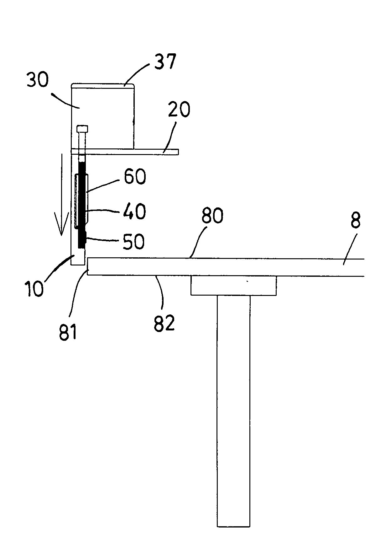
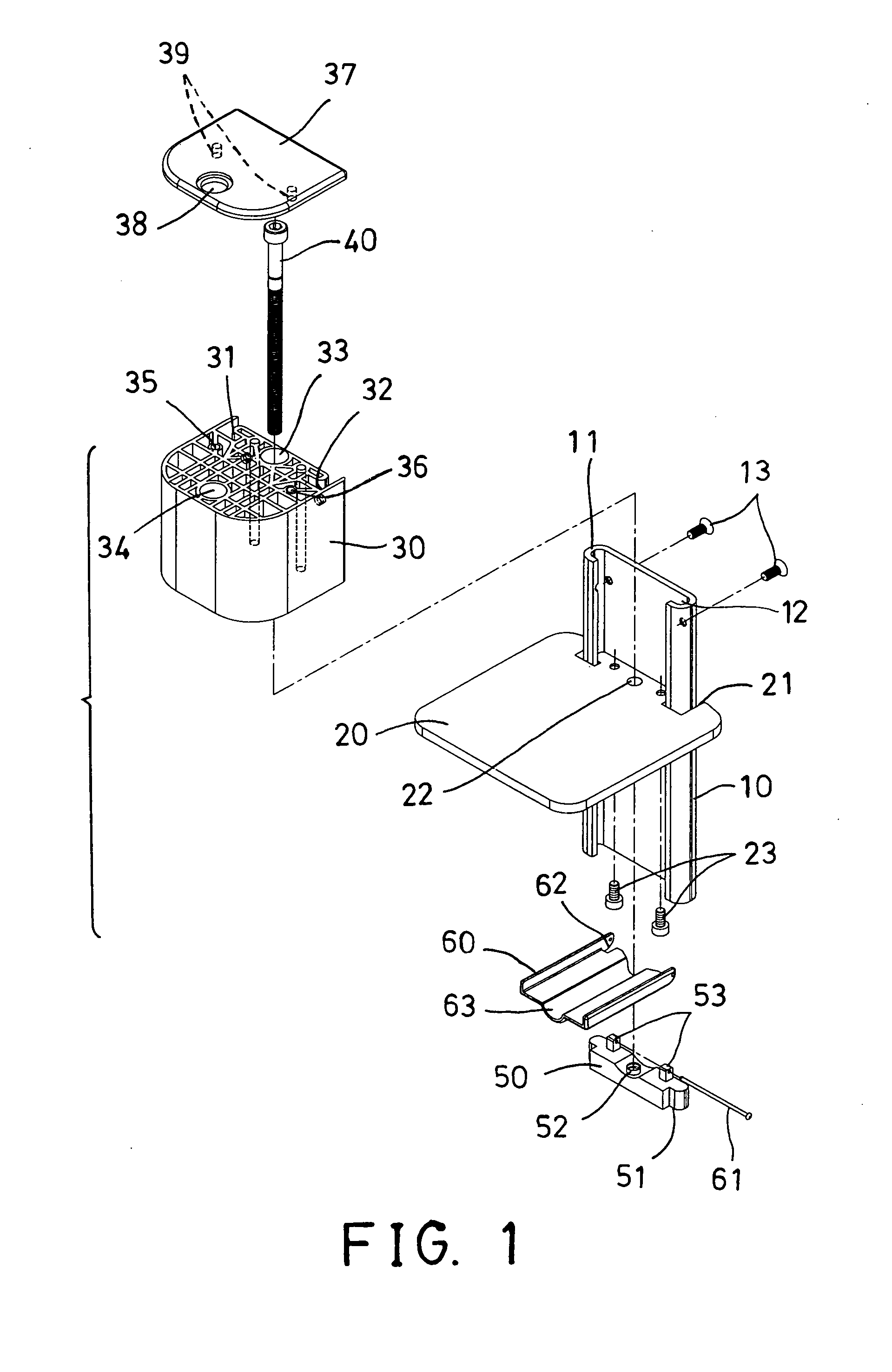
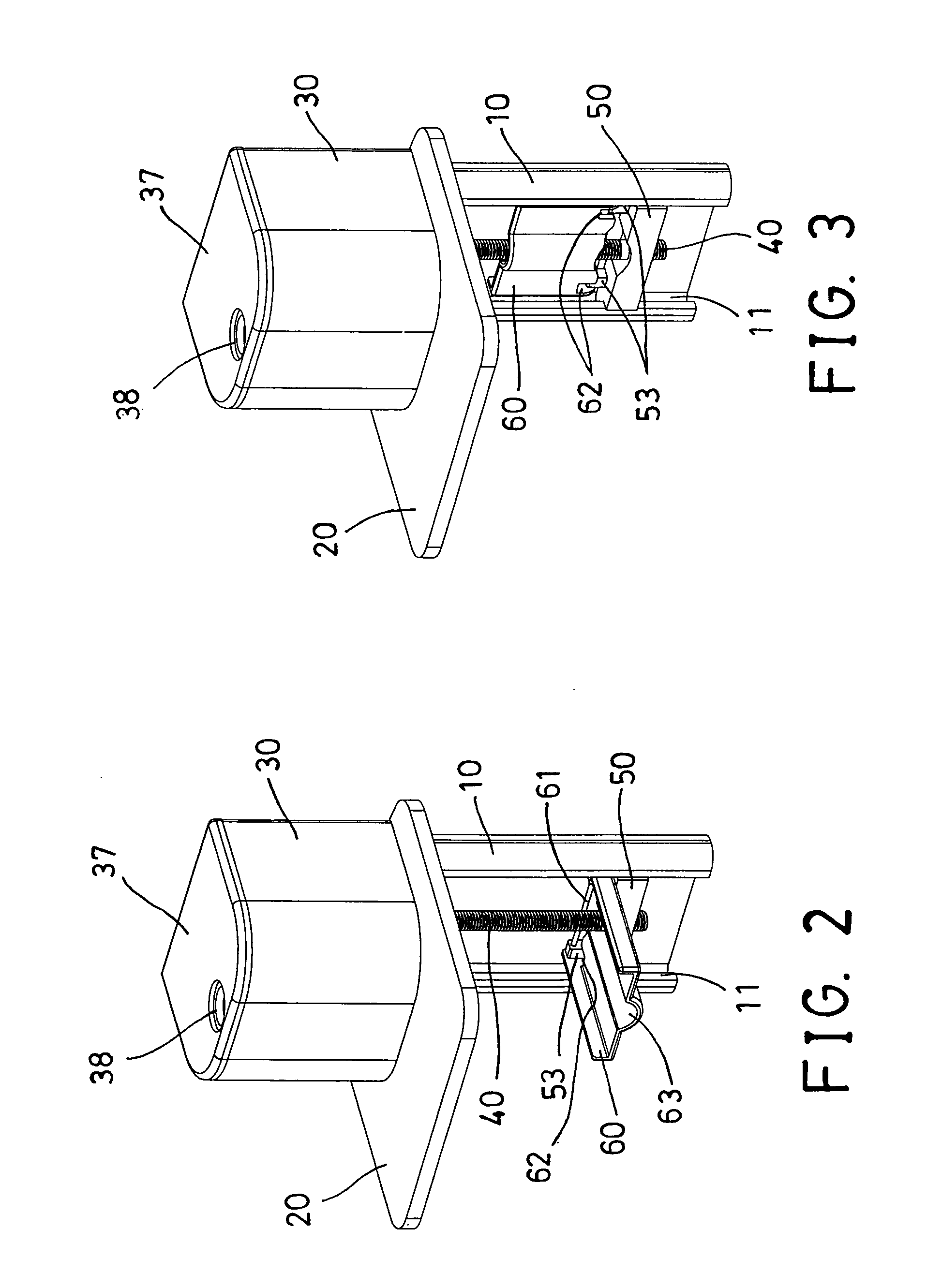
[0024]Referring to the drawings, and initially to FIGS. 1-4, a screw clamp in accordance with the present invention comprises a carrier or support plate or member 10 disposed or arranged perpendicular to a table top or table plate 8 (FIGS. 4-7) and to be attached or mounted or secured onto the table plate 8, and including one or more (such as two) side tracks 11, 12 oppositely formed therein, such as oppositely formed in the side portions thereof for forming a substantially C-shaped structure. A base plate 20 includes one or more (such as two) engaging notches 21 formed therein for engaging with the tracks 11, 12 of the carrier member 10 and for attaching or mounting or securing or coupling to the carrier member 10 and for being engaged onto and supported on the upper surface 80 of the table plate 8.

[0025]As best shown in FIGS. 4-7, the base plate 20 is substantially perpendicular to the carrier member 10 and to be engaged onto and supported on the upper surface 80 of the table plat...


PUM


Abstract

A screw clamp includes a seat secured to a carrier member, a follower attached to the carrier member, an anchoring board pivotally attached to the follower for allowing the carrier member and the anchoring board to be engaged through a tiny space beside an edge portion of a table plate, and a screw engaged in the seat and engaged with the follower for allowing the follower to be moved relative to the carrier member by rotating the screw relative to the seat and for allowing the anchoring board to be moved toward the seat with the screw, and for allowing the screw clamp to be easily actuated or operated by the user.

Description

BACKGROUND OF THE INVENTION[0001]1. Field of the Invention[0002]The present invention relates to a screw clamp or carrier or support device, and more particularly to a screw clamp or carrier or support device including an improved structure arranged for allowing the screw clamp or carrier or support device to be easily actuated or operated by the user, and including a pivotal anchoring board pivotal or rotatable relative to a carrier member for allowing the carrier member and the anchoring board to be engaged through a tiny space beside an edge portion of a table plate.[0003]2. Description of the Prior Art[0004]Typical screw clamps comprise a C-shaped clamp body, and a bolt or screw threaded and attached or mounted to one end of the clamp body and movable or adjustable toward the other end of the clamp body for attaching or mounting or securing or clamping the clamp body onto various supporting members or tables.[0005]For example, U.S. Pat. No. 2,461,687 to Hopfeld, U.S. Pat. No. 3,...

Claims


Application Information

Patent Timeline
IPC IPC(8): F16B2/12
CPCF16B2/12
Inventor HO, CHIH FENG
Owner 安歌科技(集团)股份有限公司
Why Eureka
Try Eureka