Power source apparatus and vehicle equipped with the power source apparatus

Inactive Publication Date: 2013-03-28
SANYO ELECTRIC CO LTD
View PDF7 Cites 6 Cited by
  • Summary
  • Abstract
  • Description
  • Claims
  • Application Information

AI Technical Summary

Benefits of technology

[0019]In the power source apparatus of the present invention, voltage detection circuitry 4 in a sub-battery block 1B can be provided with a multiplexer 13 to switch the battery 11 for voltage detection in the high-voltage battery assembly 2, and an A/D converter 15 to convert multiplexer 13 output to a digital signal. Voltage signals converted to digital signals by the A/D converter 15 can be transmitted to the main battery block 1A via the voltage signal line 14. Since the voltages of a plurality of batteries can be detected by multiplexer switching and the detected signals can be converted to digital signals for transmission to the main battery block, voltages of the batteries that make up the sub-battery block high-voltage battery assembly can be accurately transmitted from the sub-battery block to the main battery block. This is because voltage signals are sent from the sub-battery block to the main battery block as dig

Problems solved by technology

Since the power source apparatus described above has voltage detection circuitry and a CPU provided in each battery block, a power source apparatus made up of many battery blocks has the drawback of high overall cost.
Further, a high output voltage power source apparatus does not connect high-voltage battery assembly ground lines to the ch

Method used


Image

  • Power source apparatus and vehicle equipped with the power source apparatus
  • Power source apparatus and vehicle equipped with the power source apparatus
  • Power source apparatus and vehicle equipped with the power source apparatus

Examples


Example

[0032]The following describes embodiments of the present invention based on the figures. However, the following embodiments are merely specific examples of a power source apparatus and vehicle equipped with the power source apparatus representative of the technology associated with the present invention, and the power source apparatus and vehicle of the present invention are not limited to the embodiments described below.

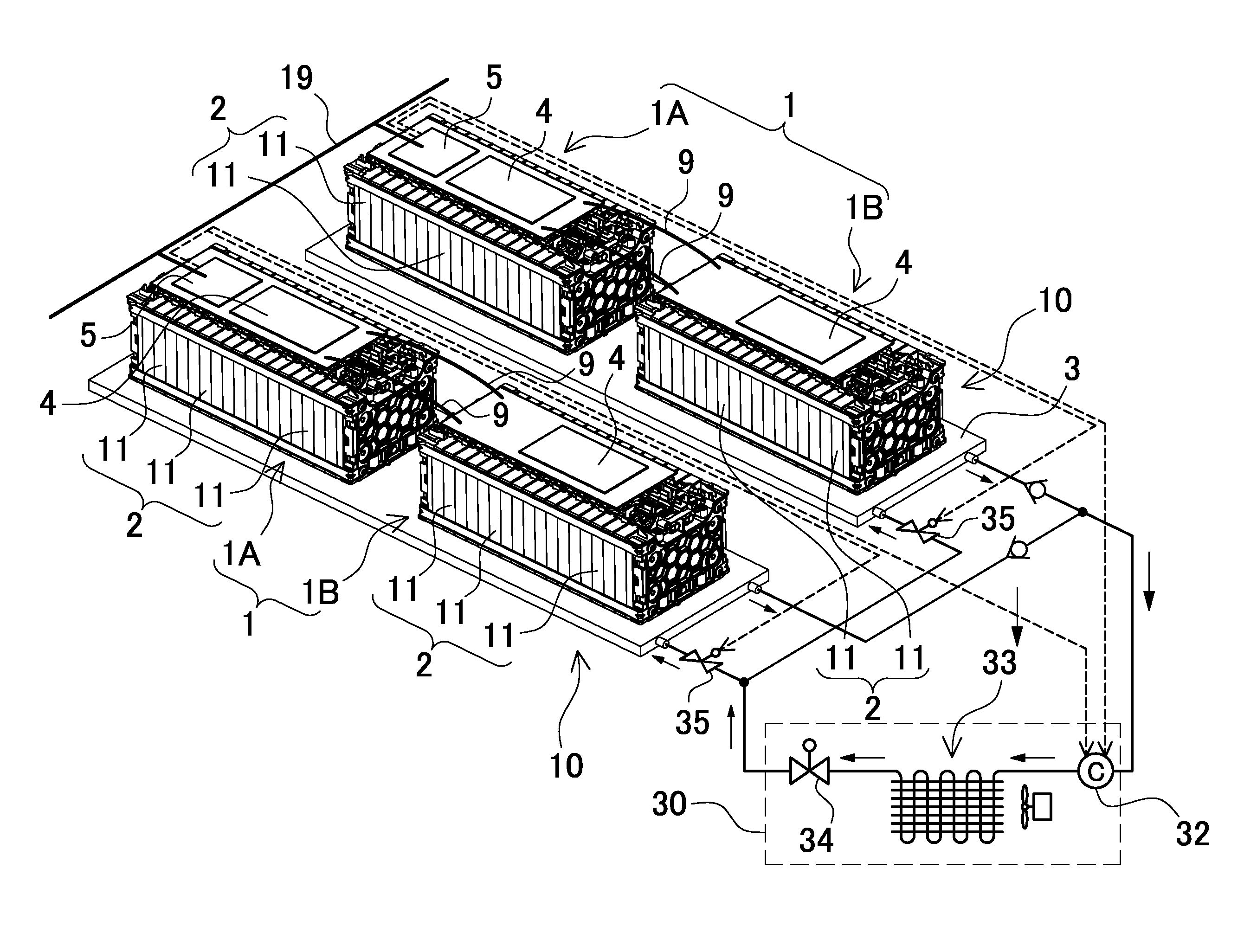
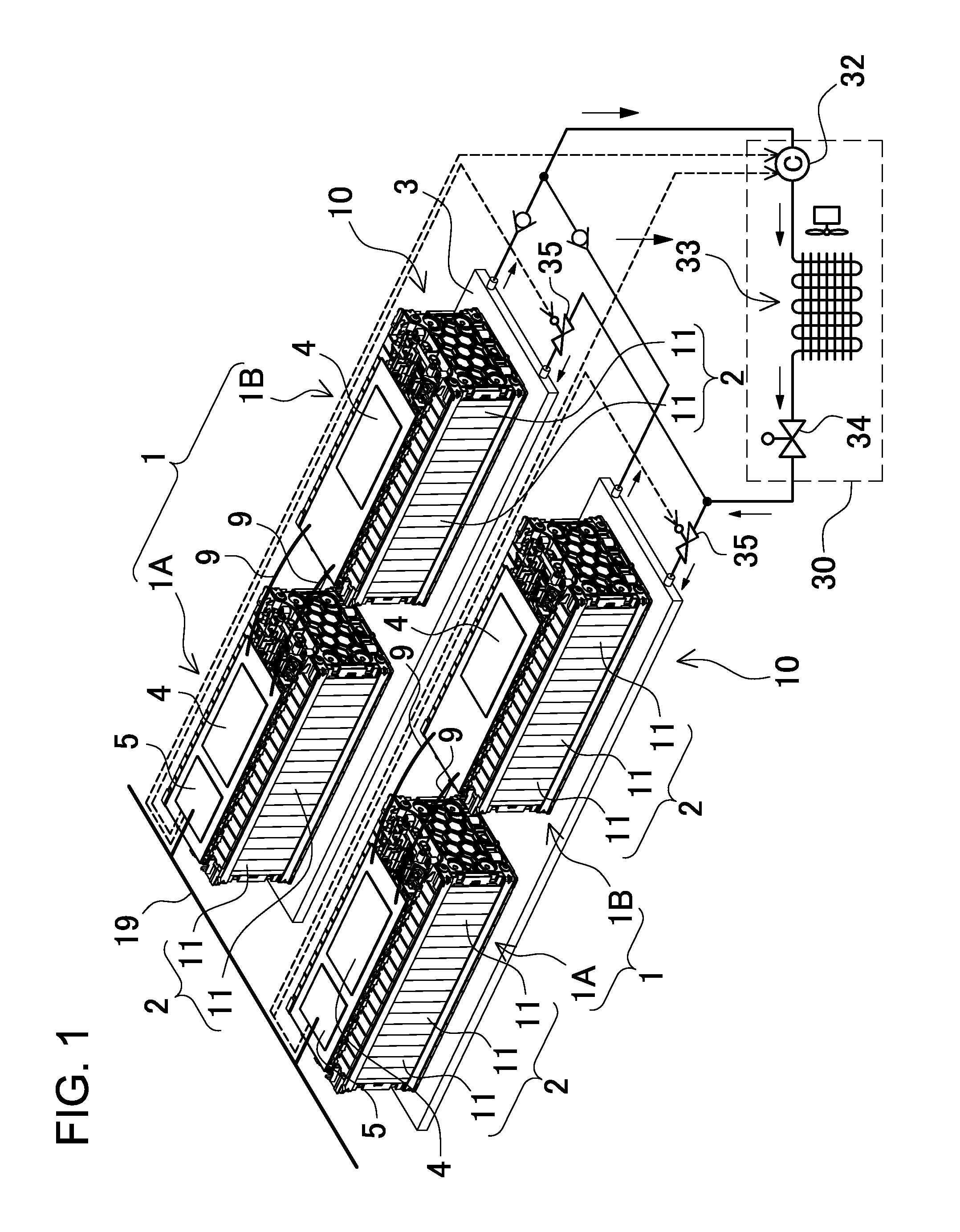
[0033]The power source apparatus shown in FIG. 1 is provided with a plurality of battery units 10. In FIG. 1, the power source apparatus has two battery units 10. Each battery unit 10 has a plurality of battery block 1 high-voltage battery assemblies 2 mounted on a cooling plate 3 in a thermally coupled manner. In FIG. 1, each battery unit 10 has two battery blocks 1 mounted on a cooling plate 3. Battery blocks 1 are connected in series or parallel and connected to an output line 19. In the power source apparatus of FIG. 1, the two battery blocks 1 mounted on a cool...


PUM


Abstract

The power source apparatus is provided with a plurality of battery blocks 1 having high-voltage battery assemblies 2 with chargeable batteries 11 connected together, voltage detection circuitry 4 to detect voltage via detection lines 17 connected to the batteries 11 that make up the high-voltage battery assemblies 2, and central processing units (CPUs) 5 to compute battery 11 state from the voltages detected by the voltage detection circuitry 4 and to issue battery 11 state signals to externally connected electrical equipment. Battery blocks 1 are main battery blocks 1A with CPUs 5 installed, and sub-battery blocks 1B connected to the main battery blocks 1A via connecting lines 9 and having no CPUs 5. The main battery block 1A detects the voltages of batteries 11 that make up a high-voltage battery assembly 2 in the sub-battery block(s) 1B.

Description

BACKGROUND OF THE INVENTION[0001]1. Field of the Invention[0002]The present invention relates to a power source apparatus with a plurality of battery blocks connected in series or parallel to increase output, and in particular, to a power source apparatus where each battery block is provided with circuitry to detect battery voltages, and to a vehicle equipped with the power source apparatus.[0003]2. Description of the Related Art[0004]A power source apparatus required to output high power has a plurality of battery blocks connected in series or parallel to increase the output voltage and current. This type of power source apparatus can have a plurality of battery blocks connected in series to increase output voltage and / or a plurality of battery blocks connected in parallel to increase output current. The battery blocks have high-voltage battery assemblies with a plurality of batteries connected in series to increase voltage. This type of power source apparatus is primarily used in ...

Claims


Application Information

Patent Timeline
IPC IPC(8): H02J9/00B60L1/00B60L3/00B60L11/18G01R19/00G01R31/36H01M2/10H01M10/48H01M10/60H01M10/613H01M10/625H01M10/633H01M10/6567H02J7/02H02J7/10
CPCB60L3/0046Y10T307/615B60L11/126B60L11/1864B60L11/1874B60L11/1879B60L2210/30B60L2210/40B60L2240/545B60L2270/142Y02T10/7005Y02T10/7077Y02T10/7241Y02T10/7061Y02T10/6217B60L3/0069B60L50/62B60L50/64B60L58/14B60L58/15B60L58/18B60L58/21B60L58/26Y02T10/62Y02T10/70Y02T10/72Y02T10/7072
Inventor KUNIMITSU, TOMONORIWATANABE, TSUYOSHITANAKA, KUNIHO
Owner SANYO ELECTRIC CO LTD
Why Eureka
Try Eureka