Winding configuration of doubly salient permanent magnet electric machine

a permanent magnet electric machine and winding technology, applied in the direction of dynamo-electric machines, electrical apparatus, magnetic circuit shapes/forms/construction, etc., can solve the problems of linear electric machines not suitable for precise control of location, increased and increased cost, so as to reduce the pulsation of propulsive force and attraction force, and reduce the number of permanent magnets used

Active Publication Date: 2013-03-28
KOREA ELECTROTECH RES INST
View PDF8 Cites 18 Cited by
  • Summary
  • Abstract
  • Description
  • Claims
  • Application Information

AI Technical Summary

Benefits of technology

[0021]In a doubly salient electric machine according to the present invention, a stator can be composed of permanent magnets and stator salient poles neighboring the permanent magnets, thus reducing the number of permanent magnets used compared to a conventional form.
[0022]Further, the present invention provides an electric machine in which a first mover and a second mover are arranged to be electrically spaced apart from each other by a predetermined phase angle, thus reducing the pulsation of a propulsive force and a attraction force. Th...

Problems solved by technology

However, the structure of the conventional linear electric machine is problematic in that as a movement distance is lengthened, the number of permanent magnets used is increased and then cost is inevitably increased, and in that t...

Method used


Image

  • Winding configuration of doubly salient permanent magnet electric machine
  • Winding configuration of doubly salient permanent magnet electric machine
  • Winding configuration of doubly salient permanent magnet electric machine

Examples


Embodiment Construction

[0055]Thus far, the case of a single mover 110 has been described. Hereinafter, embodiments in which a principal identical to that of the above description is applied to the case where the number of movers is two, as shown in FIGS. 7 to 11, will be described.

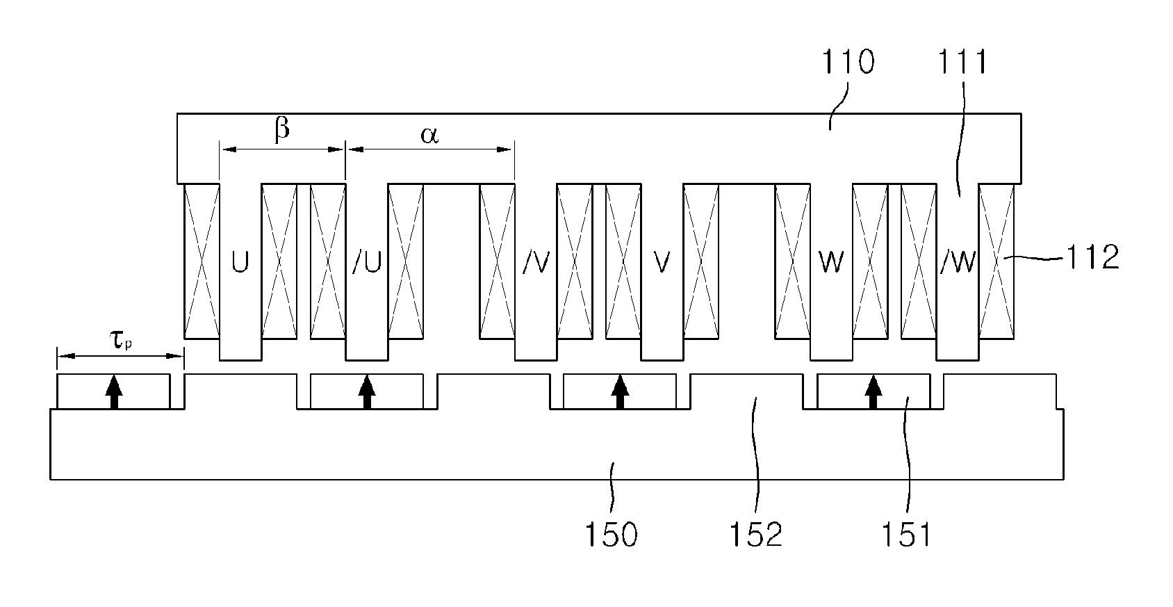
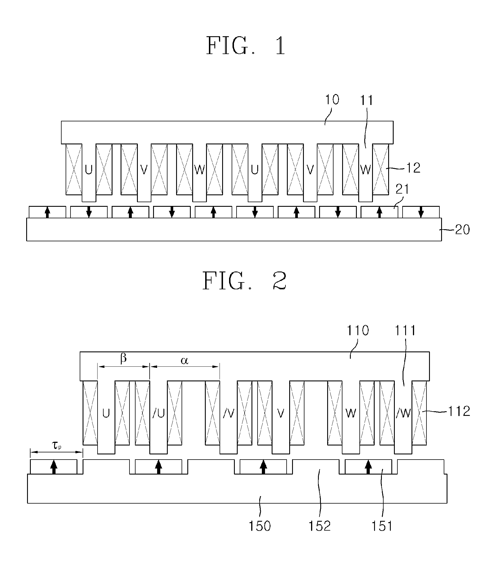
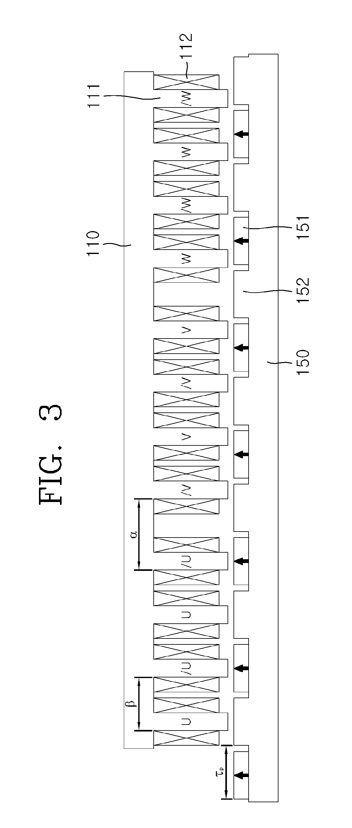
[0056]First, as shown in FIG. 7, a first mover 110 and a second mover 120 move while facing a stator 150, each mover 110 / 120 has an N (the number of power phases) multiple number of teeth 111 and phase windings 112 wound around the respective teeth, and the stator 150 includes permanent magnets 151 arranged in depressions between individual stator salient poles 152 of an iron core in which the stator salient poles 152 are formed. Here, the permanent magnets 151 have the same polarity, and all of the permanent magnets can be arranged as either N-pole or S-pole permanent magnets. A method of arranging the teeth 111 formed in the first mover 110 and the second mover 120 and a method of arranging the phase windings 112 wound around ...


PUM


Abstract

The present invention relates to a doubly salient permanent magnet electric machine that has a winding structure in which series-connected windings are included in the phase windings of a mover, and that has a stator implemented as an iron core having a plurality of permanent magnets and a plurality of stator salient poles neighboring the permanent magnets, thus reducing the number of permanent magnets by half. An electric machine is configured such that a mover moves while facing a stator and includes an N (a number of power phases) multiple number of teeth and phase windings wound around the teeth, and one or more pairs of phase windings of the mover mutually having a phase difference of 180° are connected in series, and the stator includes permanent magnets in depressions between individual stator salient poles of an iron core in which the stator salient poles are formed.

Description

TECHNICAL FIELD[0001]The present invention relates, in general, to the structure of a doubly salient permanent magnet electric machine and, more particularly, to a doubly salient permanent magnet electric machine that has a winding structure in which series-connected windings are included in the phase windings of a mover, and that has a stator implemented as an iron core having a plurality of permanent magnets and a plurality of stator salient poles neighboring the permanent magnets, thus reducing the number of permanent magnets by half.BACKGROUND ART[0002]FIG. 1 illustrates an example of a conventional electric machine. Referring to FIG. 1, the conventional electric machine is an example of a permanent magnet linear synchronous motor, and includes a mover 10 having phase windings 12, in which U, V, and W phases are repeated on a mover iron core 11 having a three multiple number of teeth, and a stator 20 in which permanent magnets 21 are arranged on a linear stator iron core without...

Claims


Application Information

Patent Timeline
IPC IPC(8): H02K3/28H02K16/02
CPCH02K1/14H02K1/2746H02K21/16H02K16/02H02K2213/03H02K2213/12H02K3/28H02K41/031
Inventor CHUNG, SHI UKJEONG, YEON HOWOO, BYUNG CHULLEE, JI YOUNG
Owner KOREA ELECTROTECH RES INST
Why Eureka
Try Eureka