
Automatic rotating display system based on windows operating system

a display system and windows technology, applied in computing, instruments, portable computers, etc., can solve the problems of general difficulty in developing applications based on windows operating systems, and develop an automatic rotating display system based on windows operating system becomes an urgent technical problem to be solved

Inactive Publication Date: 2013-03-28
HONG FU JIN PRECISION IND (SHENZHEN) CO LTD +1
View PDF2 Cites 1 Cited by
  • Summary
  • Abstract
  • Description
  • Claims
  • Application Information

AI Technical Summary

Benefits of technology

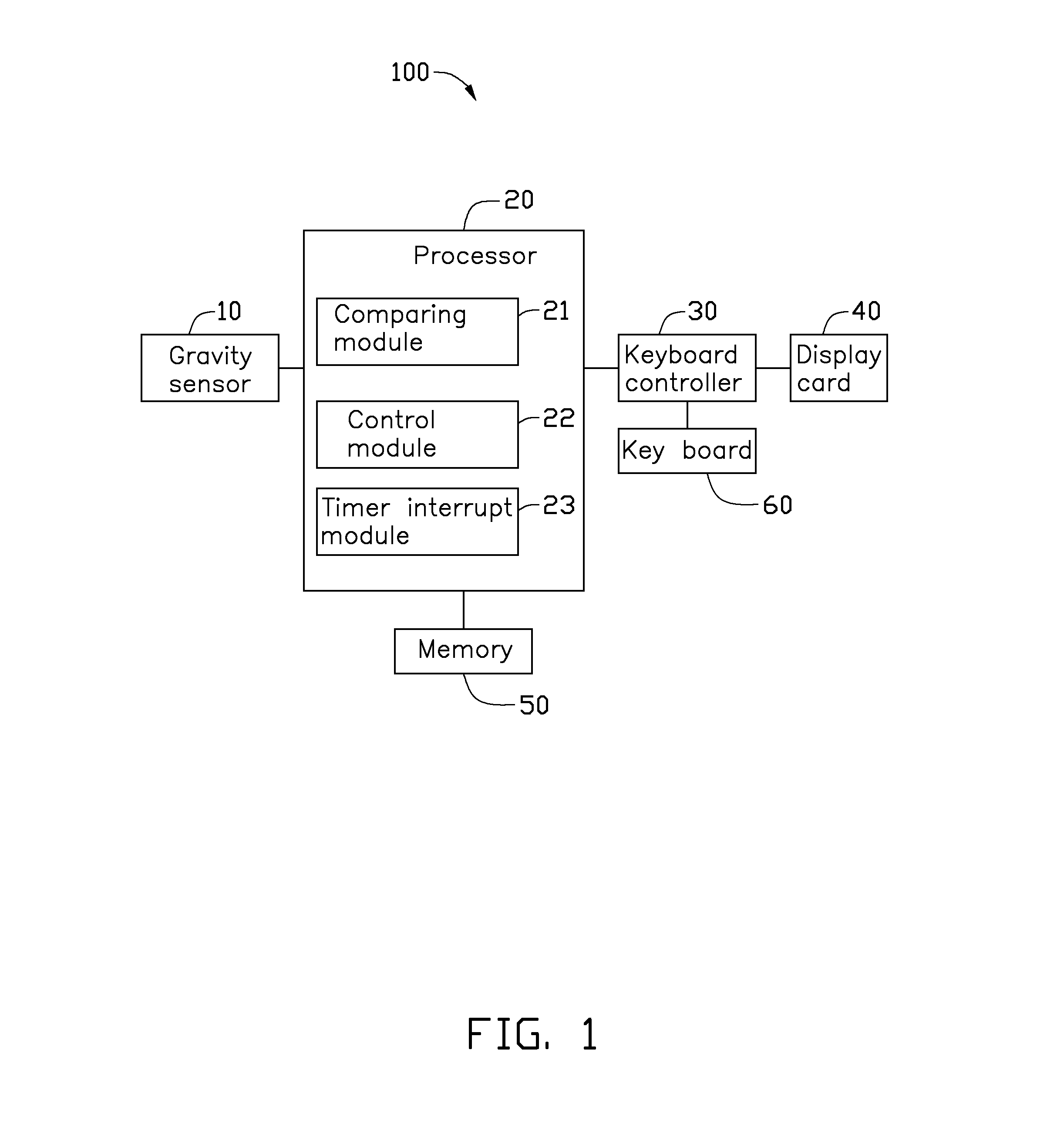
The present disclosure relates to an automatic rotating display system for electronic devices based on windows operating system. The system includes a gravity sensor, processor, keyboard controller, display card, memory, and keyboard. The gravity sensor senses positional variations of the electronic device and generates sensing signals, which are processed by the processor and outputted as control signals to the keyboard controller. The keyboard controller is responsible for receiving and translating the control signals into directional control instructions for the keyboard. The system allows for automatic rotation of the display based on the direction and magnitude changes of the electronic device. The technical effect of the invention is to provide an improved automatic rotating display system for electronic devices based on windows operating system.

Problems solved by technology

Since the source code of the Windows operating system is not available to the public, the resources cannot be shared, thus, it is generally hard to develop some applications based on the Windows operating system.
Furthermore, developing an automatic rotating display system based on the Windows system platform then becomes an urgent technical problem to be solved.

Method used


Image

  • Automatic rotating display system based on windows operating system
  • Automatic rotating display system based on windows operating system
  • Automatic rotating display system based on windows operating system

Examples


Embodiment Construction

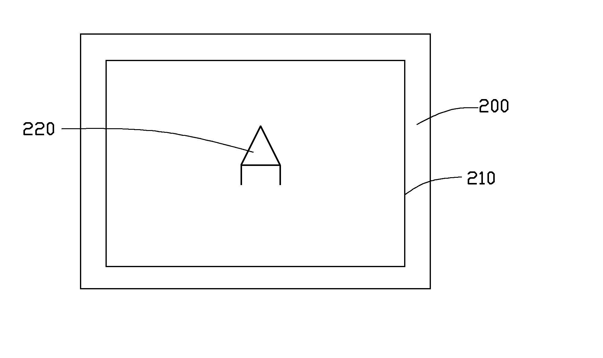
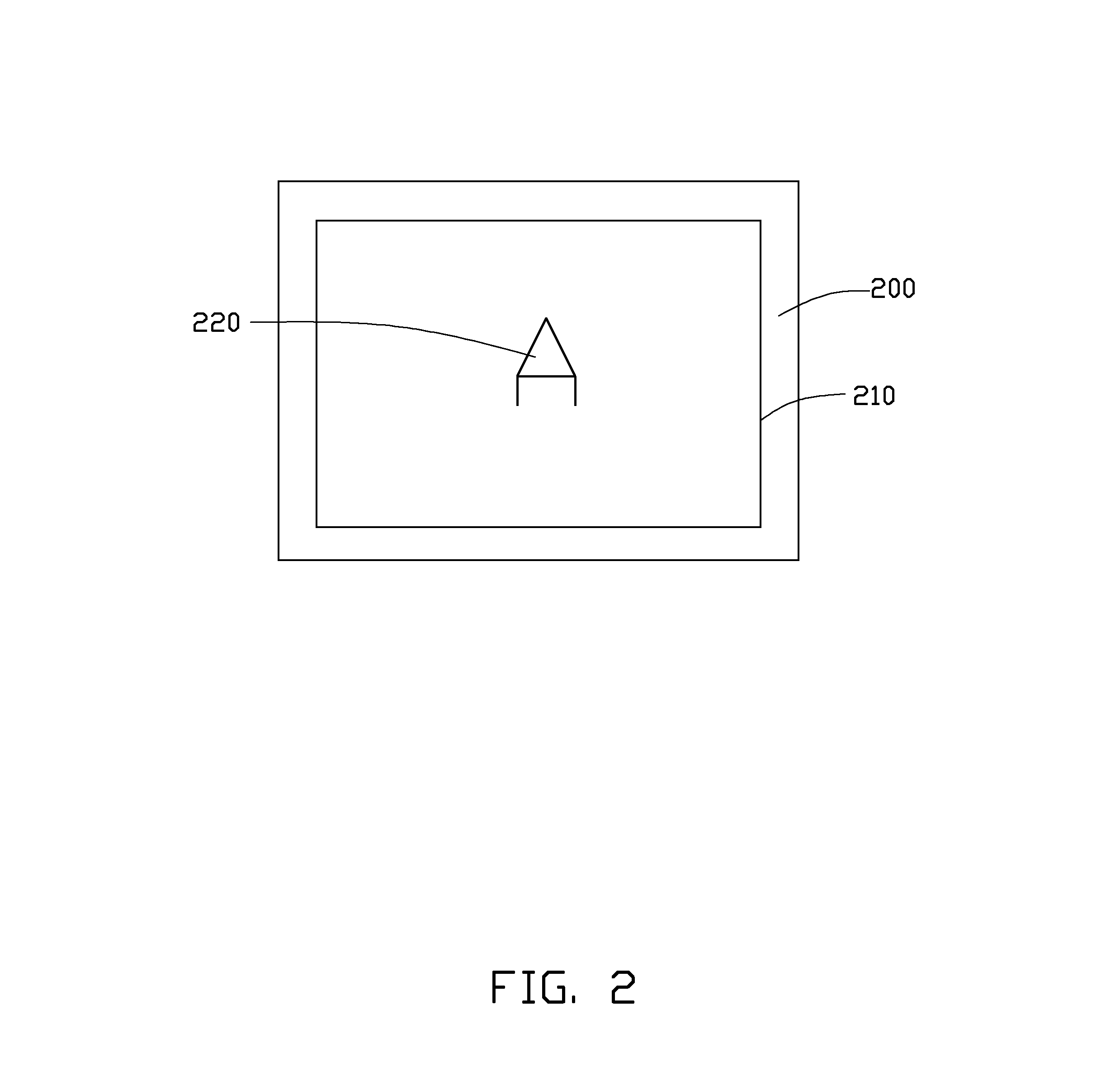
[0010]Referring to FIGS. 1 and 2, an embodiment of an automatic rotating display system 100 based on windows operating system is shown. The automatic rotating display system 100 is adapted to an electronic device 200 using the windows operating system, for controlling an image 220 displayed on a display 210 of the electronic device 200 for rotation. The automatic rotating display system 100 includes a gravity sensor (G-sensor) 10, a processor 20, a keyboard controller 30, a display card 40, a memory 50 and a keyboard 60. The gravity sensor 10, the processor 20, the keyboard controller 30 and the display card 40 are electrically connected with each other in that order. The memory 50 is electrically connected with the processor 20, and the keyboard 60 is electrically connected with the keyboard controller 30, respectively.

[0011]The gravity sensor 10 is configured for sensing or detecting a plurality of different positional variations of the electronic device 200, and generating corres...


PUM


Abstract

An automatic rotating display system is adapted to an electronic device based on a windows operating system. The electronic device includes a display for displaying one or more images. The automatic rotating display system includes a gravity sensor, a processor, a keyboard controller and a display card. The gravity sensor is configured for sensing or detecting different positional variations of the electronic device, and generating corresponding different sensing signals, according to the direction and magnitude changes of the electronic device. The processor electrically connects with the gravity sensor for receiving and processing the sensing signals. The keyboard controller connects with the processor for receiving the directional control signals and translating the directional control signals into directional control instructions. The display card connects with the keyboard controller for receiving the directional control instructions and driving the image shown on the display to rotate.

Description

BACKGROUND[0001]1. Technical Field[0002]The present disclosure generally relates to automatic rotating display systems, and particularly to an automatic rotating display system based on windows operating system.[0003]2. Description of Related Art[0004]Since the source code of the Windows operating system is not available to the public, the resources cannot be shared, thus, it is generally hard to develop some applications based on the Windows operating system. Furthermore, developing an automatic rotating display system based on the Windows system platform then becomes an urgent technical problem to be solved.[0005]Therefore, there is room for improvement within the art.BRIEF DESCRIPTION OF THE DRAWINGS[0006]The components in the drawings are not necessarily drawn to scale, the emphasis instead being placed upon clearly illustrating the principles of the present disclosure.[0007]FIG. 1 shows a functional module block diagram of an embodiment of an automatic rotating display system b...

Claims


Application Information

Patent Timeline
IPC IPC(8): G09G5/00
CPCG09G5/00G09G2340/0464G09G2354/00G06F2200/1614G06F3/04847G06F1/1601G06F1/1613G06F3/0346
Inventor CHEN, CHUN-SHENGHE, FENG-LONGZOU, HUA
Owner HONG FU JIN PRECISION IND (SHENZHEN) CO LTD
Learn More