Real-Time Formation Anisotropy And Dip Evaluation Using Tri-Axial Induction Measurements

a triaxial induction measurement and anisotropy technology, applied in seismology for water-logging, instruments, detection using electromagnetic waves, etc., can solve the problem that the effect of the borehole/tool on the measured conductivity tensor may be very big

Active Publication Date: 2013-03-28
SCHLUMBERGER TECH CORP
View PDF2 Cites 36 Cited by
  • Summary
  • Abstract
  • Description
  • Claims
  • Application Information

AI Technical Summary

Problems solved by technology

The effects of the borehole / tool on the measured conductivity tensors may be very big, even in an oil base mud (OBM) environment.

Method used


Image

  • Real-Time Formation Anisotropy And Dip Evaluation Using Tri-Axial Induction Measurements
  • Real-Time Formation Anisotropy And Dip Evaluation Using Tri-Axial Induction Measurements
  • Real-Time Formation Anisotropy And Dip Evaluation Using Tri-Axial Induction Measurements

Examples


Embodiment Construction

[0018]Some embodiments will now be described with reference to the figures Like elements in the various figures will be referenced with like numbers for consistency. In the following description, numerous details are set forth to provide an understanding of various embodiments and / or features. However, it will be understood by those skilled in the art that some embodiments may be practiced without many of these details and that numerous variations or modifications from the described embodiments are possible. As used here, the terms “above” and “below”, “up” and “down”, “upper” and “lower”, “upwardly” and “downwardly”, and other like terms indicating relative positions above or below a given point or element are used in this description to more clearly describe certain embodiments. However, when applied to equipment and methods for use in wells that are deviated or horizontal, such terms may refer to a left to right, right to left, or diagonal relationship as appropriate.

[0019]Recent...


PUM


Abstract

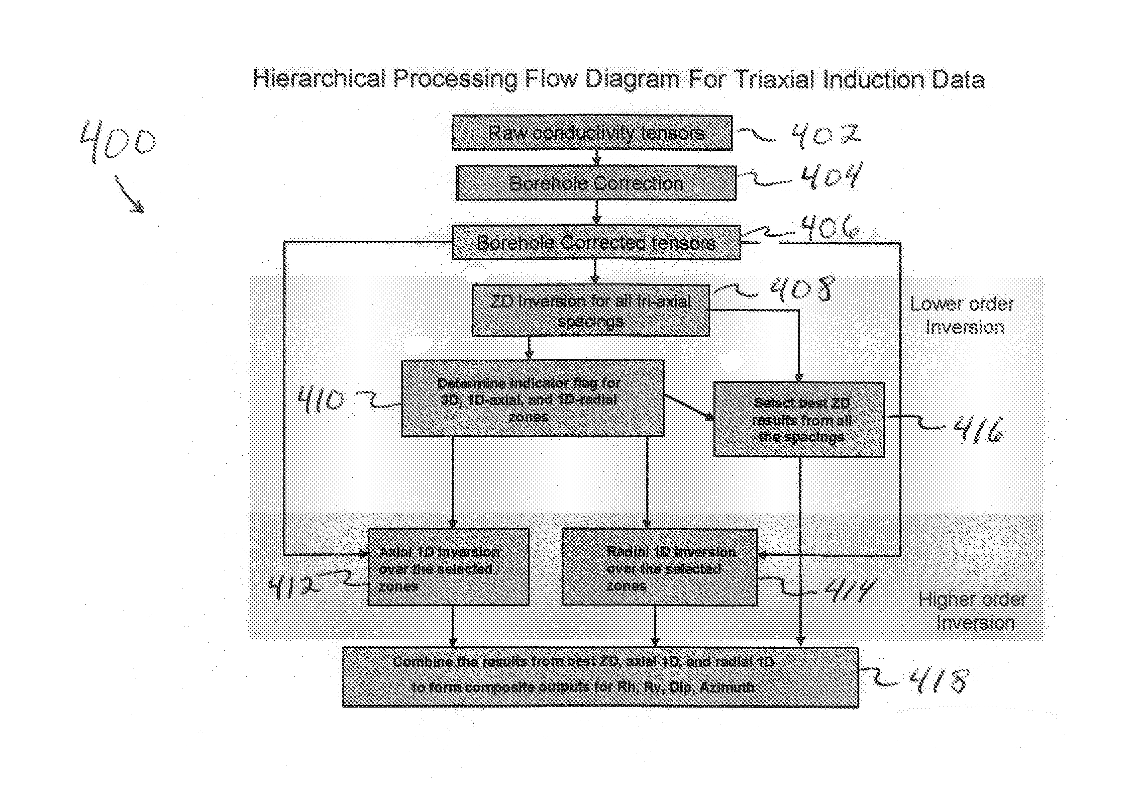
The present disclosure relates to a method to determine a formation property of a subsurface formation. A downhole logging tool having two or more tri-axial antennas is provided and used to obtain azimuthally sensitive data. Borehole correction is performed on the obtained data and a ZD-inversion is performed on the borehole corrected data for all antenna spacing groups. A formation indicator flag is determined and, depending on the determined formation indicator flag, a 1D-axial inversion and / or a 1D-radial inversion is performed over selected zones, or neither is performed. The best ZD-inversion results are selected and the 1D-axial inversion results and / or the 1D-radial inversion results, if any, are combined with the selected best ZD- inversion results to form a composite inversion result. The formation property of the subsurface formation is determined using the composite inversion result.

Description

CROSS-REFERENCE TO OTHER APPLICATIONS[0001]This application claims, under 35 U.S.C. §119(e), priority to and the benefit of U.S. Provisional Application No. 61 / 297,353, filed Jan. 22, 2010.BACKGROUND[0002]1. Technical Field[0003]The present disclosure relates generally to the logging of subsurface formations surrounding a wellbore using a downhole logging tool, and particularly to determining when higher order processing of the logging measurements is advantageous or appropriate.[0004]2. Background Art[0005]Logging tools have long been used in wellbores to make, for example, formation evaluation measurements to infer properties of the formations surrounding the borehole and the fluids in the formations. Common logging tools include electromagnetic tools, nuclear tools, and nuclear magnetic resonance (NMR) tools, though various other tool types are also used. Early logging tools were run into a wellbore on a wireline cable, after the wellbore had been drilled. Modern versions of such...

Claims


Application Information

Patent Timeline
Patent Type & Authority Applications(United States)
IPC IPC(8): G01V3/12G06F19/00G16Z99/00
CPCG01V1/42G06F19/00G01V3/12G01V3/30G16Z99/00
Inventor WU, PETER T.BARBER, THOMAS D.
Owner SCHLUMBERGER TECH CORP
Why Eureka
Try Eureka