Method and apparatus for determining the shape of an earth borehole and the motion of a tool within the borehole

a technology of earth borehole and motion, which is applied in the direction of borehole/well accessories, instruments, surveys, etc., can solve the problems of inaccurate method description of true borehole shape, tool translation in the borehole, and often not the shape of the borehol

Inactive Publication Date: 2000-05-23
HALLIBURTON ENERGY SERVICES INC
View PDF10 Cites 110 Cited by
  • Summary
  • Abstract
  • Description
  • Claims
  • Application Information

AI Technical Summary

Problems solved by technology

A significant drawback to that method is that, in reality, the borehole shape is often not circular but is rather of an elliptical or even more complex shape.
Therefore, under many circumstances, that method does not accurately describe the true borehole shape.
Furthermore, although the methods described in the '337 and '277 patents do account for the ellipticity of a borehole and tool rotation during measurement, those methods assume that the tool does not translate in the borehole during measurement.
During drilling operations, however, the tool is rarely free from translational motion.
Thus, those methods generally do not provide satisfactory results in a measuring while drilling (MWD) mode of operation.
Additionally, the '337 and '277 patents do not account for borehole shapes that are more complex than an ellipse.
However, in modern petroleum well drilling and logging, the drill string is frequently not in a vertical orientation.
Thus, the method and apparatus of the '125 patent does not solve a significant problem in the art.

Method used


Image

  • Method and apparatus for determining the shape of an earth borehole and the motion of a tool within the borehole
  • Method and apparatus for determining the shape of an earth borehole and the motion of a tool within the borehole
  • Method and apparatus for determining the shape of an earth borehole and the motion of a tool within the borehole

Examples


Embodiment Construction

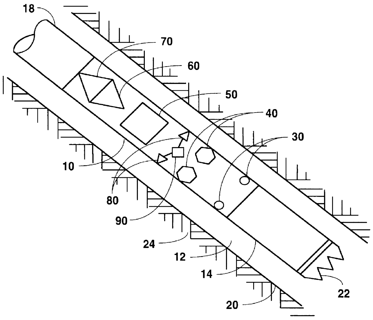
Referring to FIG. 1, a preferred embodiment of this invention comprises a tool 10, preferably an MWD tool, mounted in a section of a rotating drill string 18 disposed within a borehole 12 traversing an earth formation 24. A drill bit 22 is mounted at the bottom of the drill string 18 to facilitate the drilling of the borehole 12. Drill bit 22 is connected to the drill string 18 with a drill collar 14. Tool 10 preferably includes three distance sensors 30 (only two are shown in FIG. 1) to measure the distance from the tool 10 to the borehole wall 20 and at least one angle sensor 40 to measure the orientation of the borehole 12 with respect to a reference direction, such as the direction of the earth's gravity or the direction of magnetic north. Tool 10 also preferably includes two pairs of accelerometers 80 (only one pair is shown in FIG. 1) and a high-pass filter 90 to help define the motion of the tool 10 within the borehole 12. Additionally, tool 10 comprises a signal processor 50...


PUM


Abstract

A method and apparatus are provided for estimating the cross-sectional shape and orientation of an earth borehole and the motion of a tool therein. The method and apparatus involve measuring the distance from the tool to the borehole wall at a plurality of locations around the periphery of the tool and fitting those measured distances to a predetermined shape function using a nonlinear parameter estimation technique to minimize the error between the estimated shape of the borehole and the measured distances. The method and apparatus may be used to estimate elliptical and higher order borehole shapes. Additionally, the method and apparatus may be used while drilling the borehole.

Description

1. Field of the InventionThis invention relates generally to a method and apparatus for determining the shape and orientation of a borehole traversing an earth formation and the motion of a tool within the borehole while drilling the borehole. More specifically, this invention relates to a nonlinear parameter estimation technique used to approximate the shape of an earth borehole by measuring the distance from the tool to the borehole wall at a plurality of locations around the periphery of the tool and fitting those measured distances to a predetermined shape function in such a manner as to minimize the error between the estimated shape and the measured distances.2. Description of the Related ArtThe cross-sectional shape of a borehole traversing an earth formation is useful in ascertaining other valuable information regarding various properties of the formation, such as stress, porosity, and density. Several methods to obtain information about the shape of a borehole are described ...

Claims


Application Information

Patent Timeline
Patent Type & Authority Patents(United States)
IPC IPC(8): E21B44/00E21B47/00E21B47/022E21B47/08E21B47/02G01B15/00G01B15/04G01B21/20G01V1/52
CPCE21B44/00E21B47/02208G01V1/52G01B15/04G01B21/20E21B47/082E21B47/0224E21B47/085
Inventor MURPHEY, CAREY R.VARSAMIS, GEORGIOS L.WISNIEWSKI, LAURENCE T.CHEN, CHEN-KANG DAVID
Owner HALLIBURTON ENERGY SERVICES INC
Why Eureka
Try Eureka