Optical scanner apparatus and optical scanner control apparatus

Inactive Publication Date: 2013-04-04
MITSUMI ELECTRIC CO LTD
View PDF1 Cites 33 Cited by
  • Summary
  • Abstract
  • Description
  • Claims
  • Application Information

AI Technical Summary

Benefits of technology

The present invention is about improving optical scanners by reducing sensor interconnect noise to detect mirror inclinations accurately. The technical effect of this invention is to enhance the precision of optical scanners.

Problems solved by technology

The voltage detected by the piezo-electric sensor for detection may be interfered by a noise as the voltage detected by the piezo-electric sensor for detection when the mirror portion is being oscillated is very small.
However, according to the conventional technique, the voltage detected by the piezo-electric sensor for detection is very small and is easily interfered by a noise (crosstalk) from other signal lines.
Thus, there is a possibility that an inclination of a mirror cannot be precisely detected because of the noise (crosstalk).

Method used


Image

  • Optical scanner apparatus and optical scanner control apparatus
  • Optical scanner apparatus and optical scanner control apparatus
  • Optical scanner apparatus and optical scanner control apparatus

Examples


first embodiment

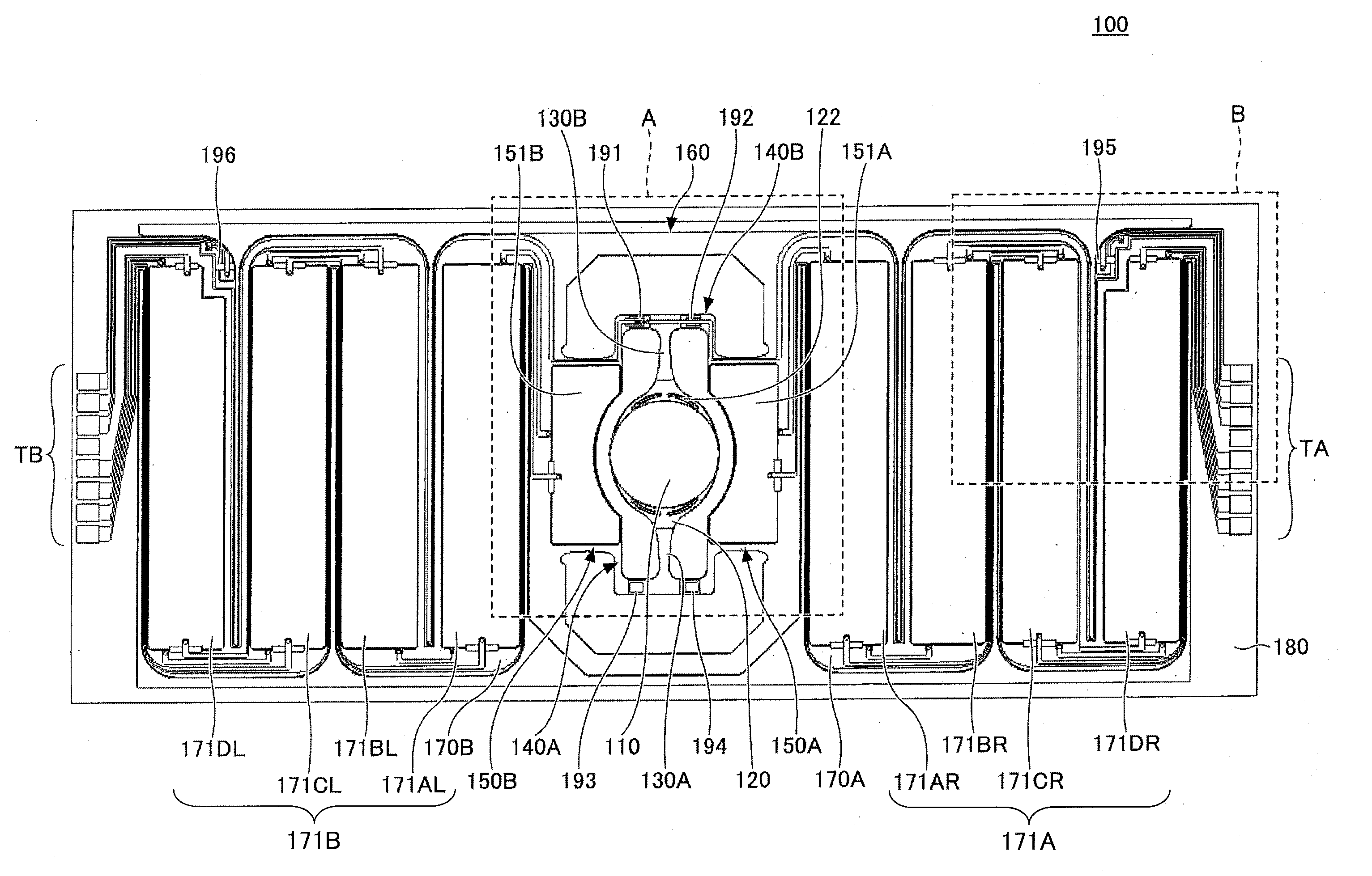
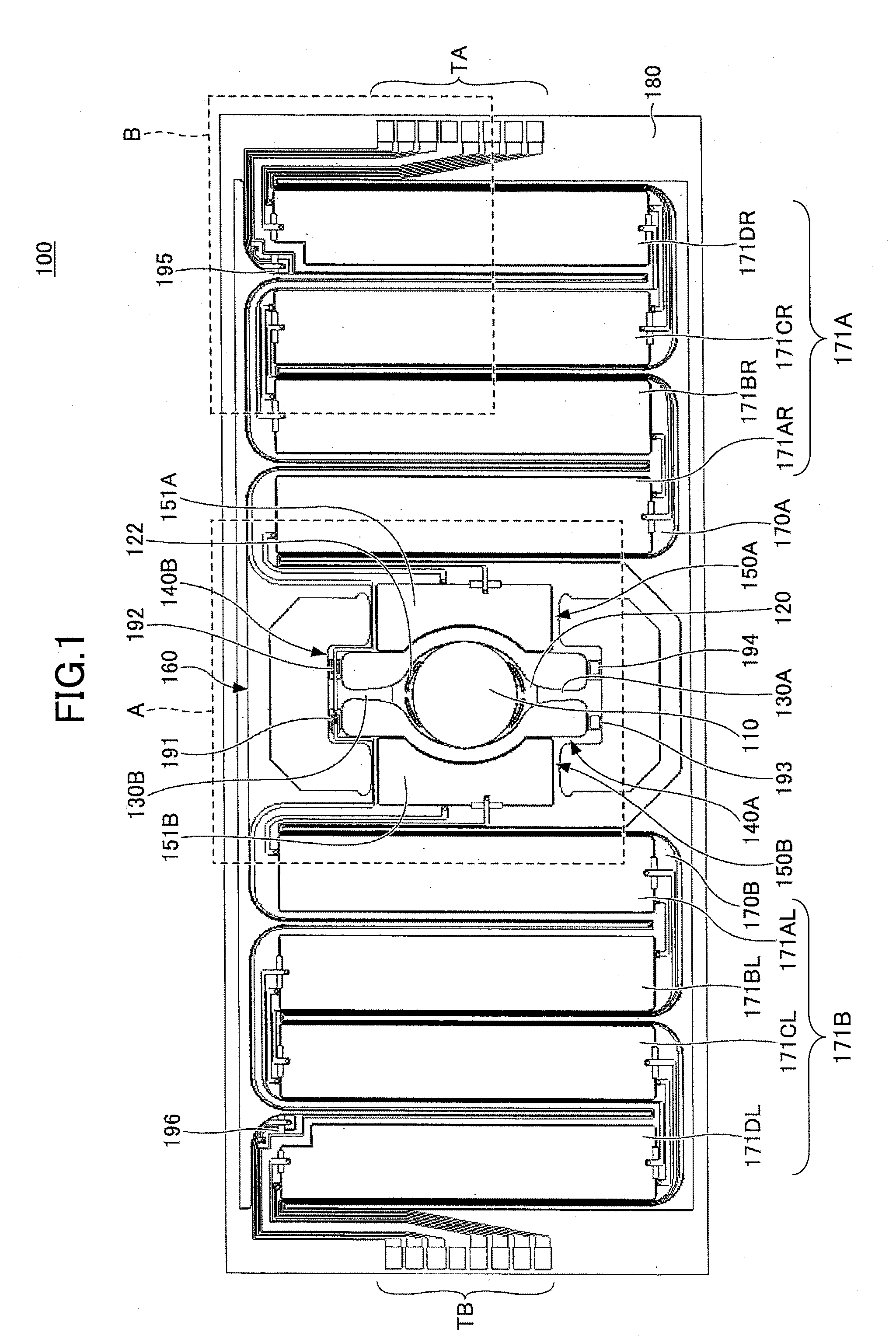
[0048]The first embodiment is explained with reference to drawings. FIG. 1 is a view showing an example of an optical scanner apparatus 100 of the first embodiment.

[0049]The optical scanner apparatus 100 of the embodiment includes a mirror 110, a mirror support portion 120, a first torsion beam 130A, a second torsion beam 130B, a first connecting beam 140A, a second connecting beam 140B, a first horizontal driving beam 150A, a second horizontal driving beam 150B, a movable frame 160, a first vertical driving beam 170A, a second vertical driving beam 170B, and a fixed frame 180.

[0050]The first horizontal driving beam 150A and the second horizontal driving beam 150B of the embodiment include a first horizontal driving source 151A and a second horizontal driving source 151B, respectively. The first vertical driving beam 170A and the second vertical driving beam 170B include a first vertical driving source 171A and a second vertical driving source 171B, respectively.

[0051]The mirror sup...

second embodiment

[0092]The second embodiment is explained with reference to drawings. The second embodiment is different from the first embodiment that a guard pattern is provided between the sensor interconnect and the drive interconnect. In the following explanation, the same components are given the same reference numerals, and explanations are not repeated.

[0093]FIG. 4 is a view showing an example of an optical scanner apparatus 100A of the second embodiment. The optical scanner apparatus 100A includes a guard pattern 220 formed between the sensor interconnects (the first sensor interconnect 201) and the drive interconnects (first drive interconnect for lower 203). Further, the optical scanner apparatus 100A includes a guard pattern 221 formed between the second sensor interconnect 202 and the second drive interconnect for lower 205.

[0094]With reference to FIG. 5, the guard patterns 220 and 221 of the embodiment are explained. FIG. 5 is a view showing an example of the guard patterns 220 and 221...

third embodiment

[0107]The third embodiment is explained with reference to drawings. The third embodiment is different from the second embodiment that the guard pattern is only provided from the vicinities of the piezo-electric sensors 195 and 196, respectively. In the following explanation, the same components are given the same reference numerals, and explanations are not repeated. FIG. 8 is a view showing an example of an optical scanner apparatus 100B of the third embodiment. The optical scanner apparatus 100B includes a guard pattern 220A and a guard pattern 221A at the piezo-electric sensor 195 side and the piezo-electric sensor 196 side, respectively.

[0108]FIG. 9 is an enlarged view of a part B2 shown in FIG. 8.

[0109]In this embodiment, the guard pattern 220A which extends along the first sensor interconnect 201 connected to the piezo-electric sensor 191 is formed from a position P3 which is in the vicinity of the piezo-electric sensor 195. The position P3 is almost the same as a starting poi...


PUM


Abstract

An optical scanner apparatus includes first and second torsion beams which support a mirror support portion supporting a mirror from both sides in an axial direction; first and second horizontal driving beams configured to include first and second horizontal driving sources, respectively, a connecting beam; a first piezo-electric sensor; first and second sensor interconnects connected to one of and the other of an upper electrode and a lower electrode of the first piezo-electric sensor, respectively, the first sensor interconnect and the second sensor interconnect being formed to extend toward the first horizontal driving beam and the second horizontal driving beam, respectively.

Description

BACKGROUND OF THE INVENTION[0001]1. Field of the Invention[0002]The present invention relates to an optical scanner apparatus and an optical scanner control apparatus.[0003]2. Description of the Related Art[0004]Conventionally, an optical scanner apparatus in which a mirror portion which reflects an input light is rotated around a rotational axis by an actuator including a lower electrode, a piezo-electric element and an upper electrode formed in this order to scan the reflected light is known. By this actuator, the mirror portion is oscillated in vertical and horizontal directions with respect to a reflection surface by applying driving voltages to the upper electrode and the lower electrode.[0005]Further, in this optical scanner apparatus, a piezo-electric sensor for detection which detects a voltage generated in the piezo-electric element of the actuator while the mirror portion is being oscillated is further provided. An inclination of the mirror portion is detected by an output...

Claims


Application Information

Patent Timeline
IPC IPC(8): G02B26/10
CPCG01B11/25G02B26/0858G01S7/4817G01C9/06G01C2009/066G02B26/101G02B26/105
Inventor TANAKA, TOYOKITAKAHASHI, SOMEISEKINE, HISAMICHIAGA, HISANORIHIBIYA, RIICHIRO
Owner MITSUMI ELECTRIC CO LTD
Why Eureka
Try Eureka