
Light head and lamp using the same and assembling method of light head

a technology of light head and lamp, which is applied in the direction of manufacturing tools, lighting and heating equipment, lighting support devices, etc., can solve the problems of inconvenient and complex assembly operation, and achieve the effect of reducing relevant costs and assembling with eas

Inactive Publication Date: 2013-04-04
CAL COMP ELECTRONICS +1
View PDF4 Cites 3 Cited by
  • Summary
  • Abstract
  • Description
  • Claims
  • Application Information

AI Technical Summary

Benefits of technology

The invention is a method for assembling a light head for a lamp without using soldering. This method makes it easier and more eye-catching to assemble the light head and reduces the number of steps required. This results in lower costs and improved efficiency. The method also eliminates the need for certain parts to be dotted and soldered, making the overall assembly process less complicated. Overall, this method simplifies the assembly process and improves the overall quality of the light head.

Problems solved by technology

Namely, the assembling operation is rather complex and inconvenient.

Method used


Image

  • Light head and lamp using the same and assembling method of light head
  • Light head and lamp using the same and assembling method of light head
  • Light head and lamp using the same and assembling method of light head

Examples


Embodiment Construction

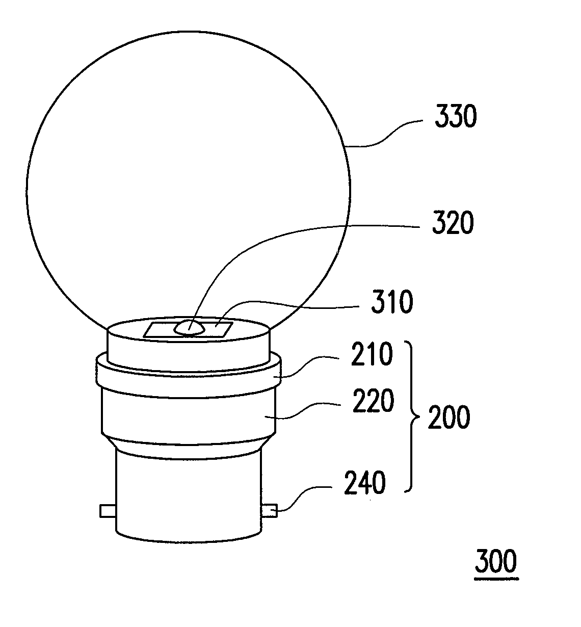
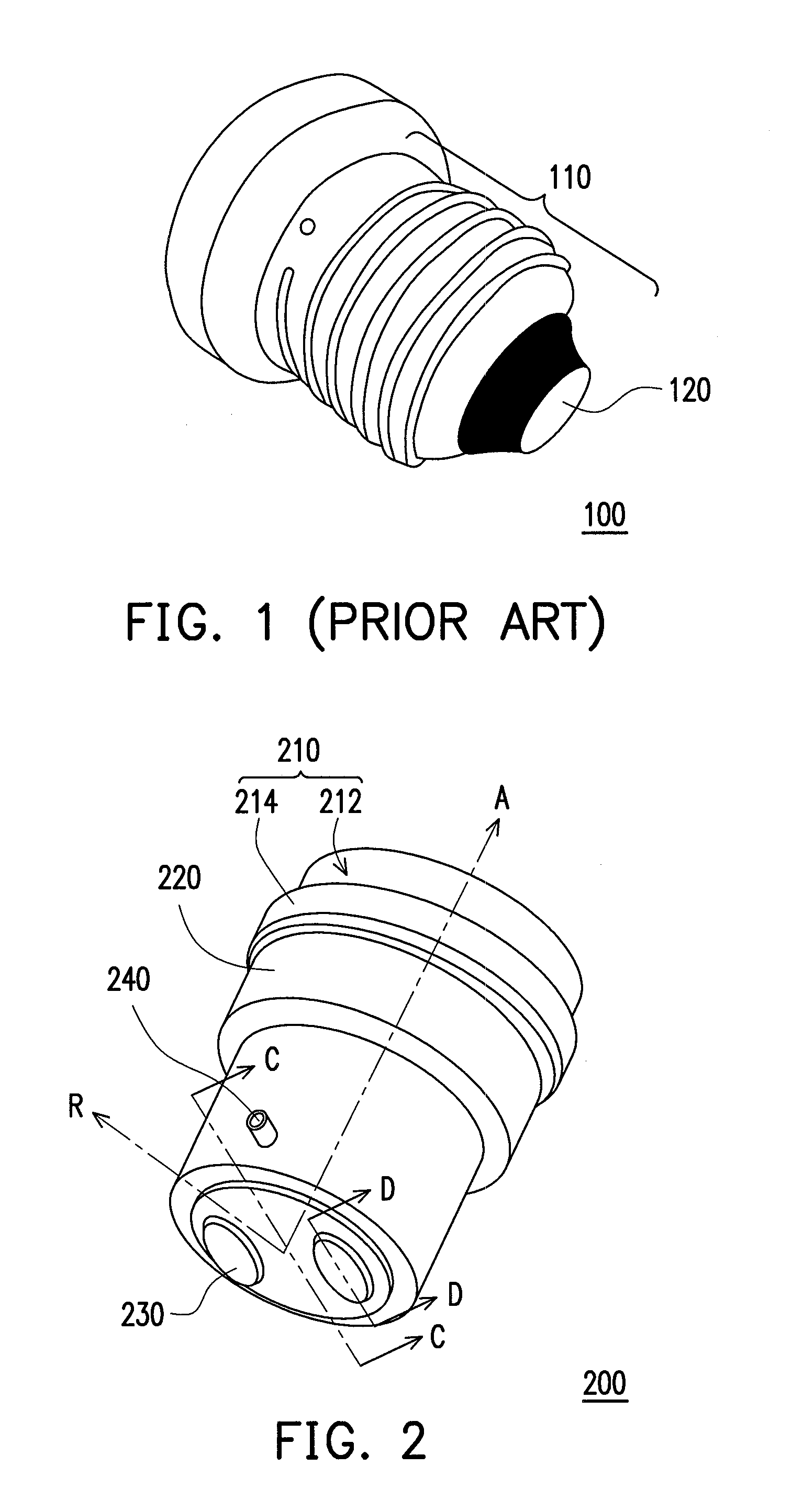
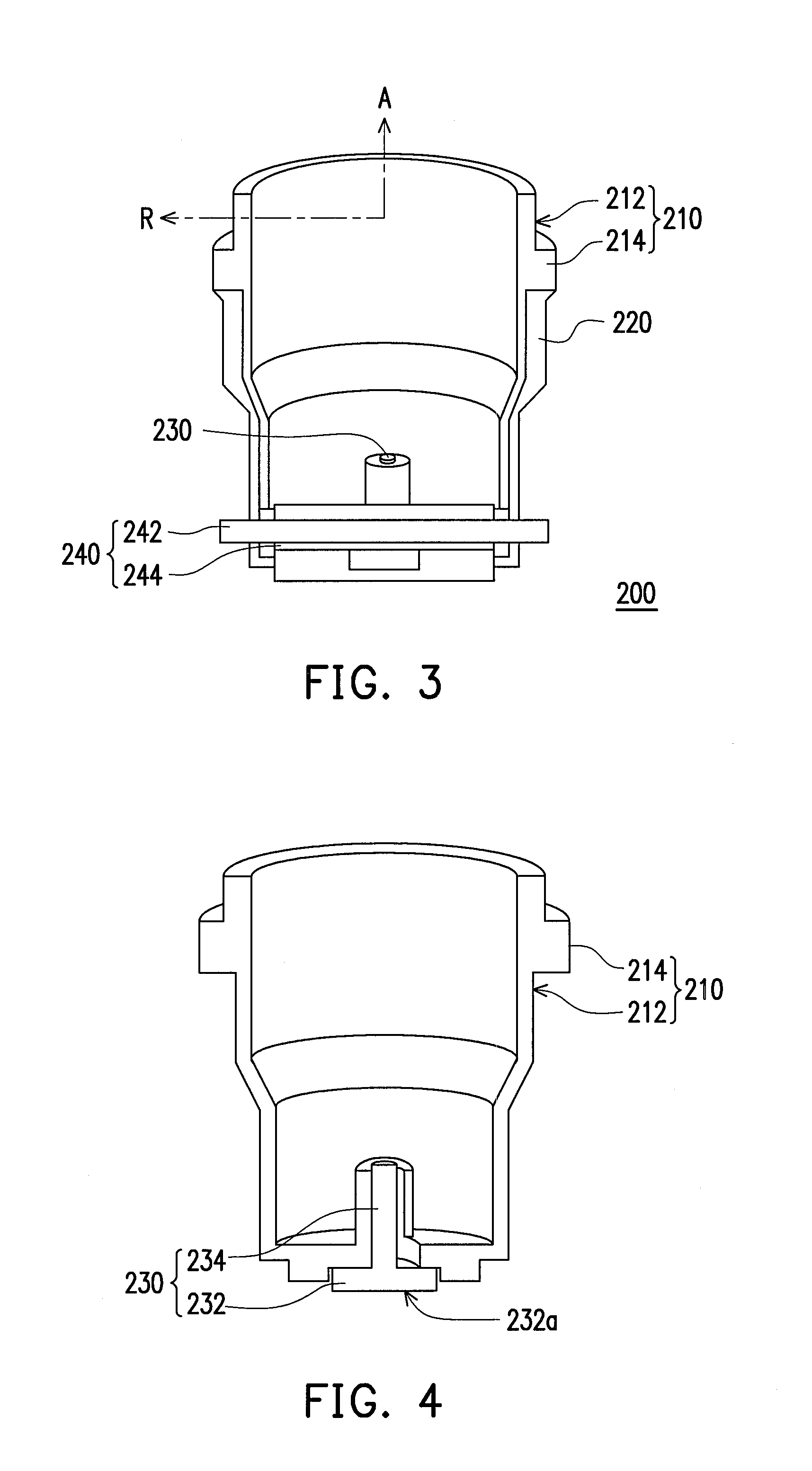
[0029]FIG. 2 is a schematic view illustrating a light head according to an embodiment of the invention. FIG. 3 is a schematic cross-sectional view taken along a sectional line C-C depicted in FIG. 2. FIG. 4 is a schematic cross-sectional view taken along a sectional line D-D depicted in FIG. 2. With reference to FIG. 2, FIG. 3, and FIG. 4, the light head 200 includes a first assembling element 210, a second assembling element 220, a plurality of first pins 230, and a second pin 240. The first assembling element 210 and the second assembling element 220 are hollow cylinders. The first assembling element 210 has an axial direction A and a radial direction R. The second assembling element 220 and the first assembling element 210 are telescoped and coaxial. The first pins 230 pass through the first assembling element 210 along the axial direction A. The second pin 240 passes through the first assembling element 210 and the second assembling element 220 along the radial direction R, so a...


PUM

PropertyMeasurementUnit
strengthaaaaaaaaaa
assembly strengthaaaaaaaaaa
structureaaaaaaaaaa

Abstract

A light head, a lamp using the light head, and an assembling method of the light head are provided. The lamp includes the light head, a circuit board, a light source, and a light cover. The circuit board is disposed on the light head and electrically connected to the light source. The light cover is assembled to the light head. The circuit board and the light source are located in the light cover. The light head includes a first assembling element, a second assembling element, first pins, and a second pin. The first assembling element has an axial direction and a radial direction. The second and first assembling elements are telescoped and are coaxial. The first pins pass through the first assembling element along the axial direction, and the second pin passes through the first and second assembling elements along the radial direction.

Description

CROSS-REFERENCE TO RELATED APPLICATION[0001]This application claims the priority benefit of Taiwan application serial no. 100135892, filed on Oct. 4, 2011. The entirety of the above-mentioned patent application is hereby incorporated by reference herein and made a part of this specification.BACKGROUND OF THE INVENTION[0002]1. Field of the Invention[0003]The invention relates to a light head, a lamp, and an assembling method. More particularly, the invention relates to a light head with an intact exterior, a lamp using the light head, and an assembling method of the light head.[0004]2. Description of Related Art[0005]Normal lamps are often equipped with light heads that are inserted into light stands for electrical connection. FIG. 1 is a schematic view illustrating a light head structure of a conventional lamp. With reference to FIG. 1, the process of assembling the light head 110 of the conventional lamp 100 is rather complicated. For instance, components are assembled together thr...

Claims


Application Information

Patent Timeline
Patent Type & Authority Applications(United States)
IPC IPC(8): F21V21/00B23P11/00
CPCY10T29/49826H01J5/52
Inventor WU, HSIEN-CHANG
Owner CAL COMP ELECTRONICS
Learn More