Allocating and deallocating portions of memory

a technology of memory and allocation, applied in the field of data processing apparatus, can solve the problems of low burden on any software using the scheme, and achieve the effects of avoiding excessive memory consumption, reducing the total number of requests, and saving tim

Active Publication Date: 2013-04-11
ARM LTD
View PDF13 Cites 56 Cited by
  • Summary
  • Abstract
  • Description
  • Claims
  • Application Information

AI Technical Summary

Benefits of technology

[0015]In some embodiments the blocks are requested to be available for allocation to the process from the kernel. They may be requested individually or several may be requested together. The requesting of blocks individually may occur where the system does not know the total resource requirements of the process and thus, rather than requesting too much memory to be allocated it is requested block by block as required. If the system knows the maximum size of the portions of memory, that is the amount of memory that is individually allocated to the process in any one allocation step then the blocks are advantageously selected to be this size or a multiple of this size. During allocation a portion is allocated to a single block, thus, if there is not room for a portion in a partially used block then the portion is allocated in the next block. This being the case it is clearly advantageous if the maximum sized portion can fit within a block. Furthermore, there may be an advantage to making the block size some multiple of the individual allocation as this may reduce the total number of requests to the kernel, and thereby save time. The multiple should however, be chosen with care to avoid excessive memory consumption. A suitable multiple may change over time and it may be advantageous to adjust this value based on past behaviour.

Problems solved by technology

Thus, not only is the management of the memory itself simplified, but the burden on any software using the scheme is also low.

Method used


Image

  • Allocating and deallocating portions of memory
  • Allocating and deallocating portions of memory
  • Allocating and deallocating portions of memory

Examples


Embodiment Construction

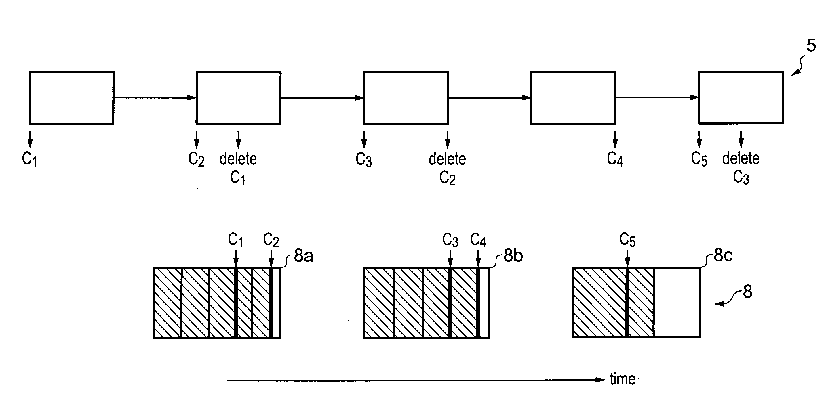
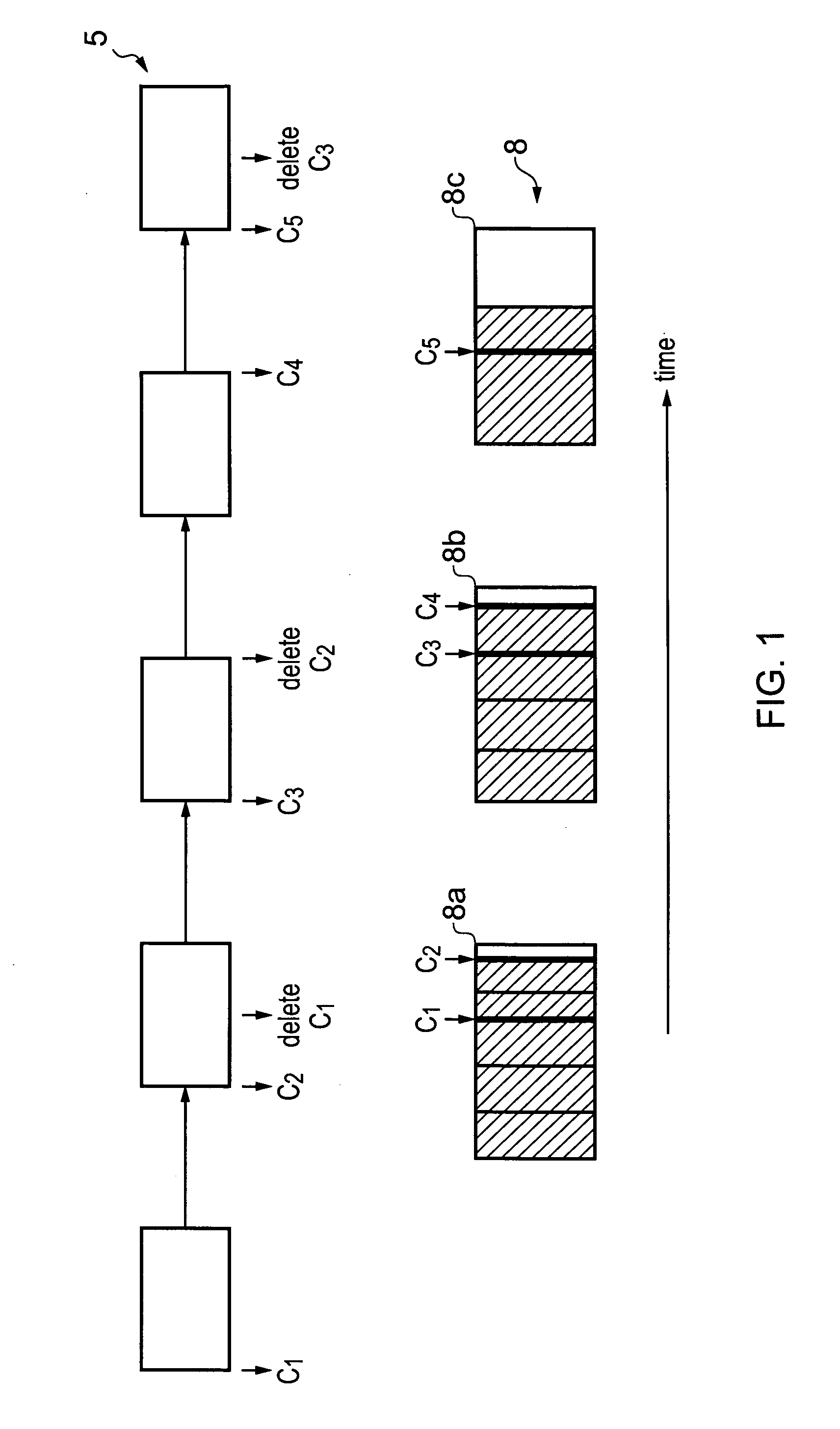
[0038]FIG. 1 schematically shows how markers are used to delimit portions of memory that have been allocated. Thus, markers or pins are set as boundaries to regions that have been allocated for use by a process. In this example, portions of memory are allocated as the process executed by the processors requests them and these portions are shown in the Figure with the vertical lines. Thus, pipeline 5 processing a process or application allocates portions of memory within memory blocks 8 as it requires them at various points of execution. It then groups some portions together and sets markers or pins C1 to C5 to mark these grouped portions or regions. The portions that are combined to form regions are selected so that they store data with a similar lifetime, thus the data stored within a region will all go out of date at the same time. The portions of the blocks that are allocated to the process are shown hashed, while those currently not allocated to a particular process are shown no...


PUM


Abstract

A method of allocating regions of memory including the steps of allocating a corresponding plurality of portions of memory for use by the process and marking regions of memory that are allocated with markers. A start of a region is marked with one of the markers and an end of a region is marked with a further one of the markers, the further one of the markers having a later relative time indication and marking a next allocated region. In response to determining that a region of allocated memory bounded by two of the markers is no longer required by the process, deleting an older of the two markers; and in response to detecting deletion of an oldest one of the markers, deallocating the region of memory up to a new oldest pending marker.

Description

BACKGROUND OF THE INVENTION[0001]1. Field of the Invention[0002]The field of the invention relates to data processing apparatus and in particular to the allocation of memory for use by processes executing on the processing apparatus.[0003]2. Description of the Prior Art[0004]Data processing apparatus use data storage to store the code executing on the processing apparatus and the data being processed. At least some of this data storage will be in the form of a memory and different portions of the memory will be allocated for different purposes. Some of this allocation may be a permanent allocation so that that portion of the memory is configured to store data for a particular purpose, while other memory allocations will be temporary. This allows flexibility in the use of memory, so that while a particular process requires storage it can have memory allocated to it, and it when it no longer has this requirement the memory portion may be deallocated making it available for allocation ...

Claims


Application Information

Patent Timeline
Patent Type & Authority Applications(United States)
IPC IPC(8): G06F12/02
CPCG06F12/0253G06F12/023
Inventor FELL, ROBIN
Owner ARM LTD
Why Eureka
Try Eureka