Wiping method for inkjet recording head

a technology of inkjet recording head and wiping method, which is applied in printing and other directions, can solve the problems of large amount of processing liquid consumed, ink consumption increases, and failure of discharge, and achieve the effect of efficient wiping

Inactive Publication Date: 2013-04-11
CANON KK
View PDF2 Cites 3 Cited by
  • Summary
  • Abstract
  • Description
  • Claims
  • Application Information

AI Technical Summary

Benefits of technology

[0010]The present invention provides a wiping method for an inkjet recording head by which processing liquid can be adequately applied to discharge-port rows in accordance with differences in ink adhesion force and by which the discharge-port rows corresponding to respective kinds of ink can be efficiently wiped.

Problems solved by technology

If the ink with the increased viscosity adheres to the discharge-port surface in areas near the discharge ports, a discharge failure may occur.
However, in such a case, a large amount of processing liquid is consumed.
Therefore, the ink consumption increases as the amount of processing liquid used in the wiping process is increased.
For some kinds of ink, the effect of the processing liquid cannot be enhanced simply by increasing the amount of processing liquid used in the wiping process.
In addition, when processing liquid with high detergency is used to remove ink with strong adhesion force, there is a risk that the discharge-port surface will be damaged in an area where ink with weak adhesion force is bonded.
In addition, some kinds of processing liquid cause other kinds of problems, such as deposition of ink components, depending on the kind of ink even if the ink bonded to the discharge-port surface can be effectively removed.
However, in such a case, the throughput of the recording operation is reduced.
If the amount of processing liquid is too small, the ink components bonded to the discharge-port surface cannot be sufficiently re-dissolved.
Thus, the ink components cannot be sufficiently removed and the recording quality is affected.
However, in such a case, throughput of the recording operation is reduced.
If the amount of processing liquid is too large, the processing liquid is consumed more than necessary and the recording costs will be increased.
Therefore, the ink consumption increases as the amount of processing liquid used in the wiping process is increased.
As a result, high costs are incurred.
However, this method is not effective if a plurality of kinds of ink are used and the adhesion tendency of ink components with respect to the temperature differs for each kind of ink.
In addition, the fluidity of the processing liquid also decreases.
As a result, the wiping performance is degraded.
However, the speed at which the ink dries on the discharge-port surface is high, and therefore the dried ink components cannot be easily re-dissolved.
This may lead to wiping failure.

Method used


Image

  • Wiping method for inkjet recording head
  • Wiping method for inkjet recording head
  • Wiping method for inkjet recording head

Examples


first embodiment

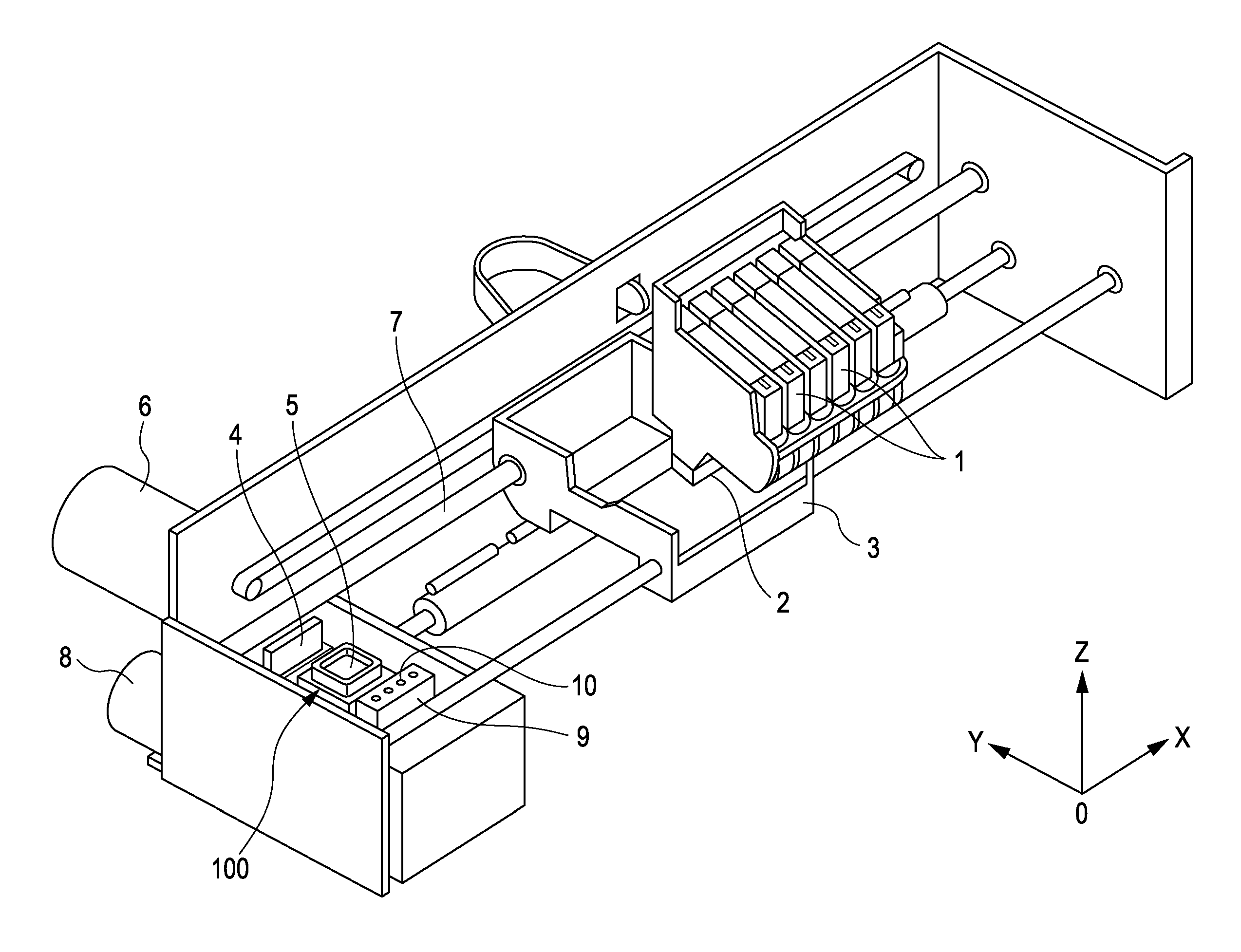
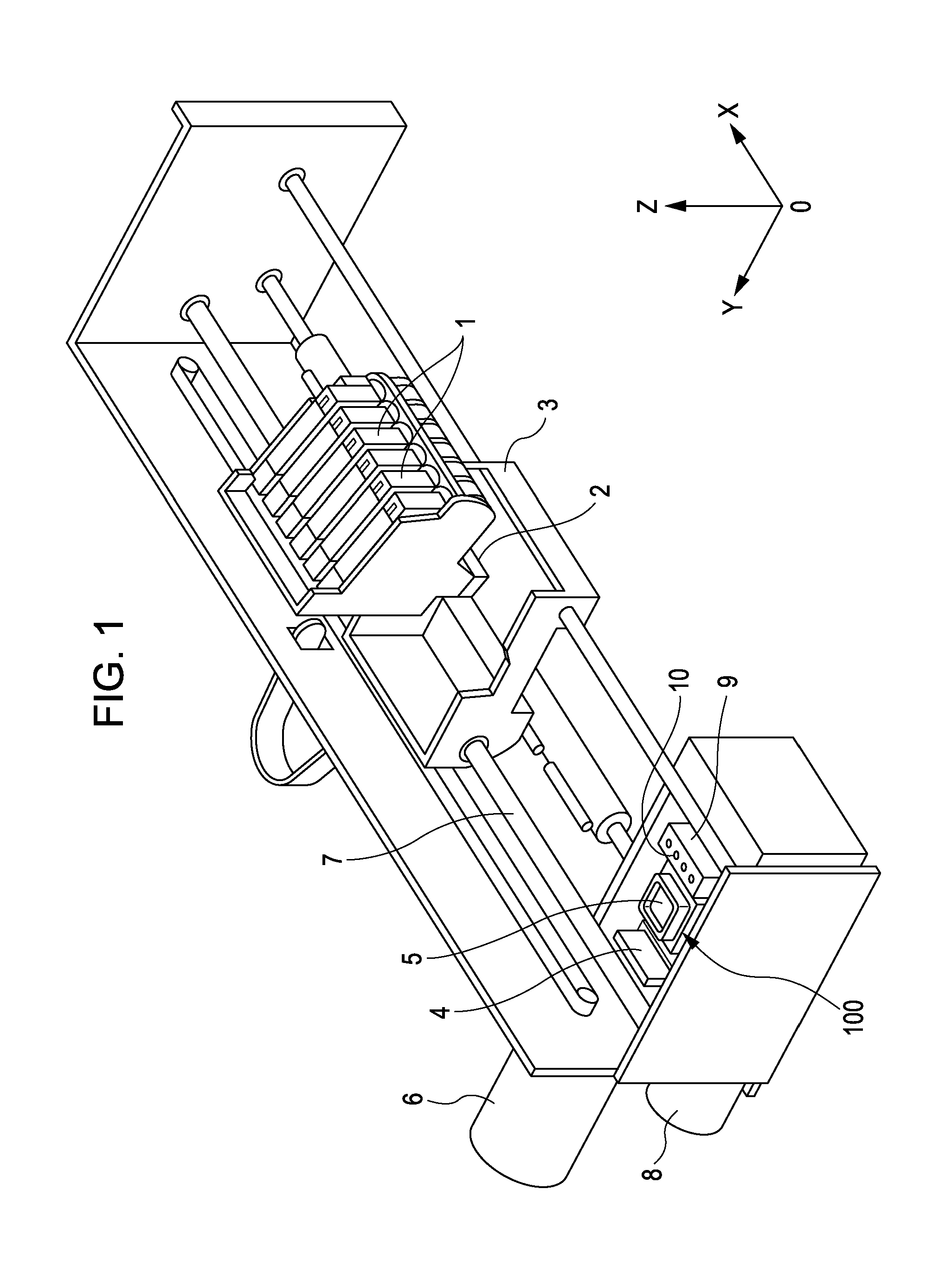
[0049]FIG. 1 is a perspective view of an inkjet recording apparatus according to a first embodiment. Referring to FIG. 1, an inkjet recording head 1 has a discharge-port surface 2 in which a plurality of discharge-port rows are formed in a predetermined pattern. The inkjet recording head 1 is mounted on a carriage 3. The carriage 3, on which the inkjet recording head 1 is mounted, is reciprocated in the X direction by a carriage motor 6 (main scanning). The carriage 3 that reciprocates is supported and guided by a guide shaft 7. A recovery unit 100 for maintaining and recovering the ink discharge performance of the inkjet recording head 1 is disposed within a movable range of the carriage 3 at a position outside a recording area.

[0050]The recovery unit 100 includes a wiper 4 for wiping the discharge-port surface 2 of the inkjet recording head 1, a cap 5 that can be tightly attached to the discharge-port surface 2 so as to cover the discharge-port rows, and a recovery-unit motor 8 fo...

second embodiment

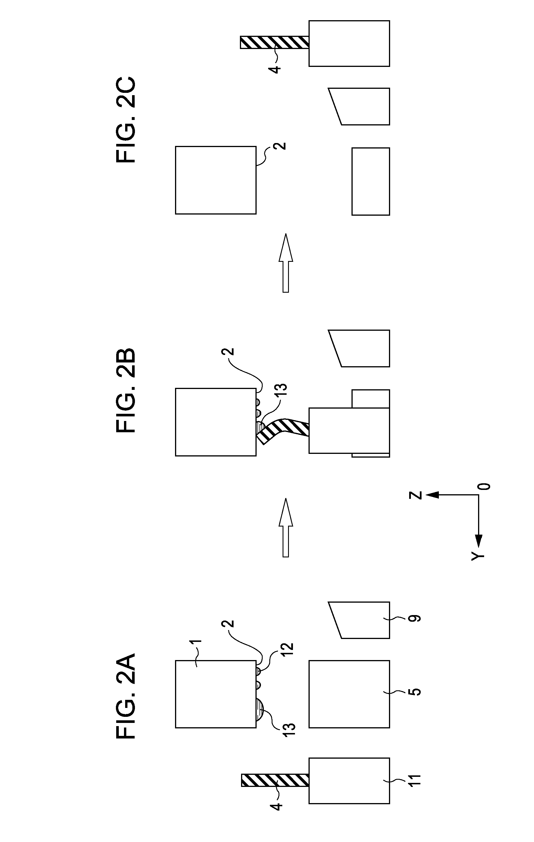
[0057]FIGS. 4A to 4F are diagrams illustrating the movement of a wiper 4 according to a second embodiment. In the present embodiment, different from the first embodiment in which the processing liquid is directly applied to the discharge-port surface 2, first, the processing liquid is applied to the wiper 4. Then, the wiping process is performed by bringing the wiper 4 to which the processing liquid is applied into contact with the discharge-port surface 2. FIGS. 4A to 4F are sectional views of FIG. 1 taken along the YZ plane. An inkjet recording apparatus according to the present embodiment is similar to the inkjet recording apparatus shown in FIG. 1 except the processing-liquid ejecting unit 9 is replaced by a processing-liquid transferring unit 22. The processing-liquid transferring unit 22 also functions as the processing-liquid applying unit. A recording head 1 of the present embodiment is similar to the recording head according to the first embodiment shown in FIG. 3. FIG. 4A ...

third embodiment

[0063]FIG. 9 is a perspective view of a wiper 4 according to the third embodiment. Referring to FIG. 9, similar to the second embodiment, the wiper 4 according to the present embodiment has slits 25 that divide a portion of the wiper 4 that comes into contact with the discharge-port surface 2 into six segments corresponding to the discharge-port rows 14 to 19. Thus, the slits 25 serve to define wiper segments 26 to 31 in the wiper 4. More specifically, a wiper segment D 26 corresponding to the discharge-port row D 14, a wiper segment E 27 corresponding to the discharge-port row E 15, a wiper segment F 28 corresponding to the discharge-port row F 16, a wiper segment G 29 corresponding to the discharge-port row G 17, a wiper segment H 30 corresponding to the discharge-port row H 18, and a wiper segment J 31 corresponding to the discharge-port row J 19 are provided. An inkjet recording apparatus according to the present embodiment is similar to the inkjet recording apparatus shown in F...


PUM


Abstract

An inkjet recording apparatus to record an image by discharging ink includes a recording head, a processing-liquid transferring unit, a wiper, and a control unit. The recording head includes, at a discharge surface, a first discharge-port row configured to discharge a first ink and a second discharge-port row configured to discharge a second ink. The processing-liquid transferring unit provides processing liquid. The wiper wipes the discharge surface, wherein the wiper includes a first wiper segment positioned to wipe the first discharge-port row and a second wiper segment positioned to wipe the second discharge-port row. The control unit moves the wiper into and out of contact force engagement with the processing-liquid transferring unit, wherein the first wiper segment receives a quantity of processing liquid from the processing-liquid transferring unit that is greater than a quantity of processing liquid received by the second wiper segment from the processing-liquid transferring unit.

Description

CROSS REFERENCE TO RELATED APPLICATIONS[0001]This application is a continuation of application Ser. No. 12 / 174,556, filed on Jul. 16, 2008, which claims the benefit of Japanese Patent Application No. 2007-185870 filed Jul. 17, 2007, which are hereby incorporated by reference herein in their entirety.BACKGROUND OF THE INVENTION[0002]1. Field of the Invention[0003]The present invention relates to a wiping method for wiping with a wiper an inkjet recording head that records an image by discharging ink.[0004]2. Description of the Related Art[0005]Recording apparatuses including recording heads for recording images on recording media on the basis of image information are generally used as printers, copy machines, facsimile machines, etc. An example of a recording apparatus is an inkjet recording apparatus that performs a recording operation by discharging ink from a discharge-port surface of a recording head. In the inkjet recording apparatus, ink contained in pressure chambers is rapidl...

Claims


Application Information

Patent Timeline
Patent Type & Authority Applications(United States)
IPC IPC(8): B41J2/165
CPCB41J2/16535B41J2/16538B41J2/16552B41J2/16541
Inventor ISHIMATSU, SHIN
Owner CANON KK
Why Eureka
Try Eureka