Brushless motor and electric pump

Inactive Publication Date: 2013-04-11
AISAN IND CO LTD
View PDF0 Cites 3 Cited by
  • Summary
  • Abstract
  • Description
  • Claims
  • Application Information

AI Technical Summary

Benefits of technology

The present patent describes a technique that improves the connection between the teeth and the yoke in a brushless motor. This technique prevents poor connections between the teeth and the yoke and evens out the intervals between the teeth and the outside surface of the rotor. This results in a more stable and durable motor.

Problems solved by technology

With the brushless motor described in the above described art, a manufacturing error or the like may cause a variation in lengths of the plurality of teeth connected to the yoke.
As a result, a variation is created in magnetic resistances among the teeth and causes a decline in motor efficiency or vibration during rotation of the motor.
Therefore, in a part of the teeth, a force is generated in a direction that releases the connection of the teeth with the yoke and impairs the connecting conditions between the teeth and the yoke.
As a result, a poor connection readily occurs between the teeth and the yoke and a variation in magnetic resistances is readily created among the teeth.

Method used


Image

  • Brushless motor and electric pump
  • Brushless motor and electric pump
  • Brushless motor and electric pump

Examples


Embodiment Construction

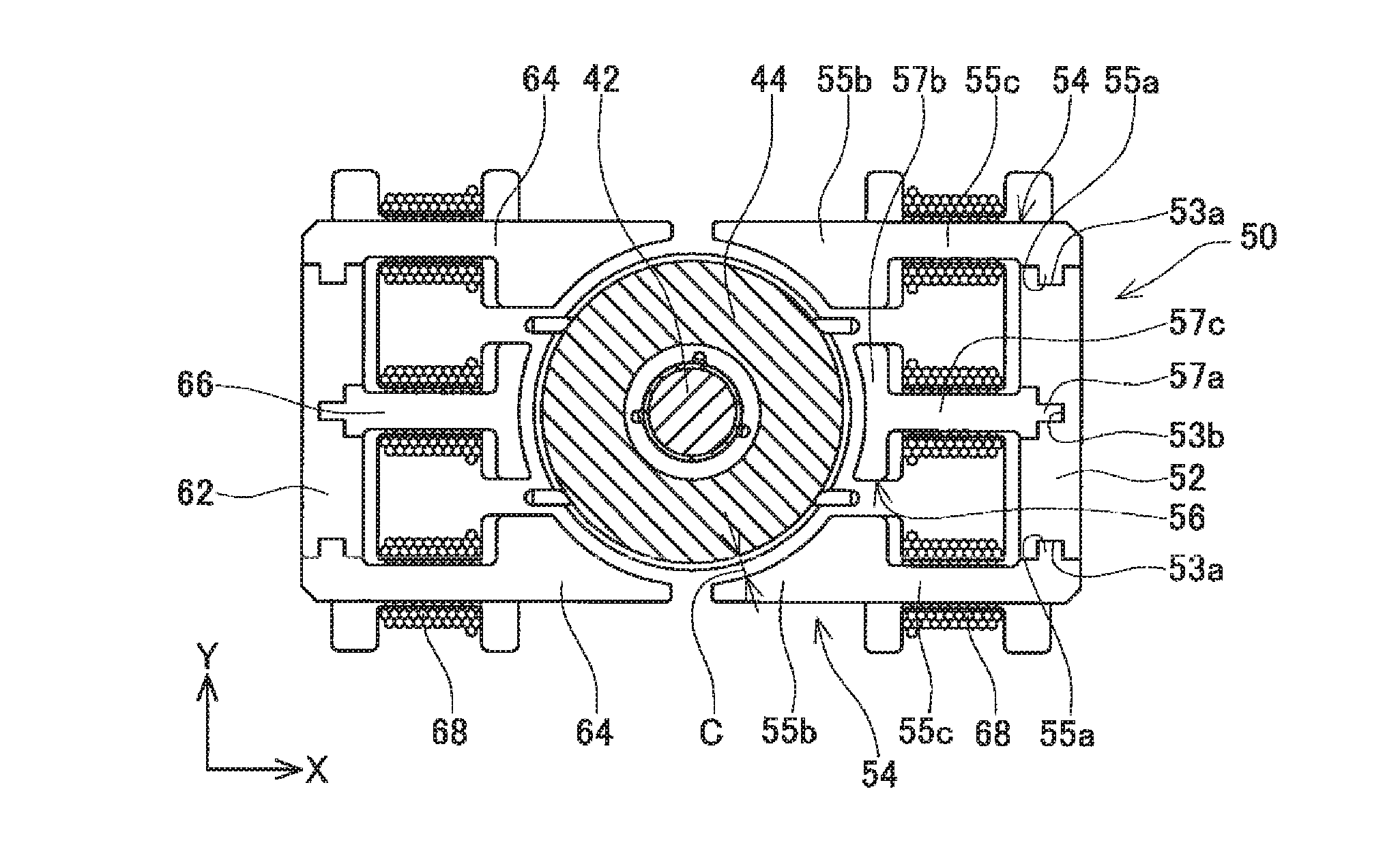
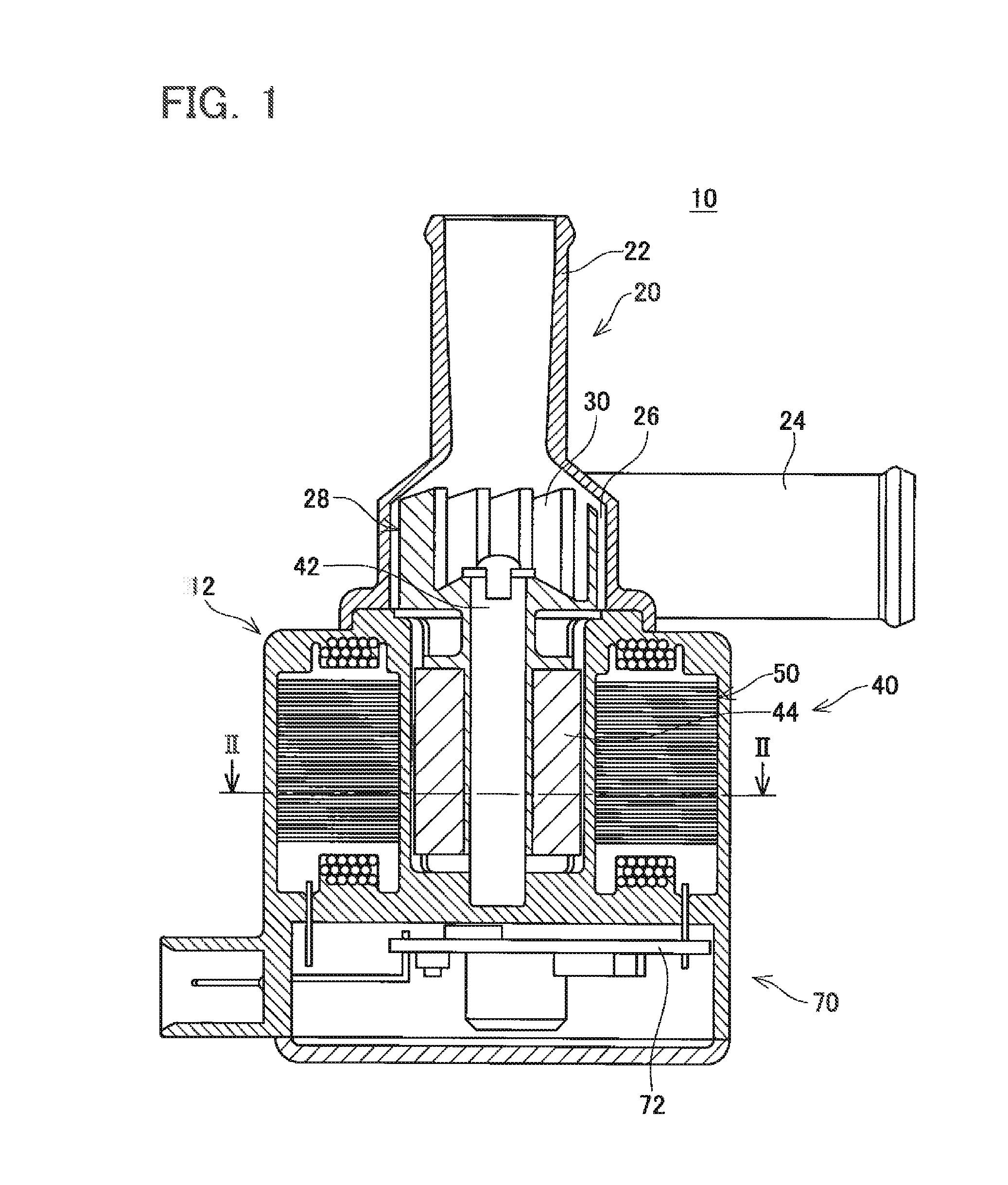
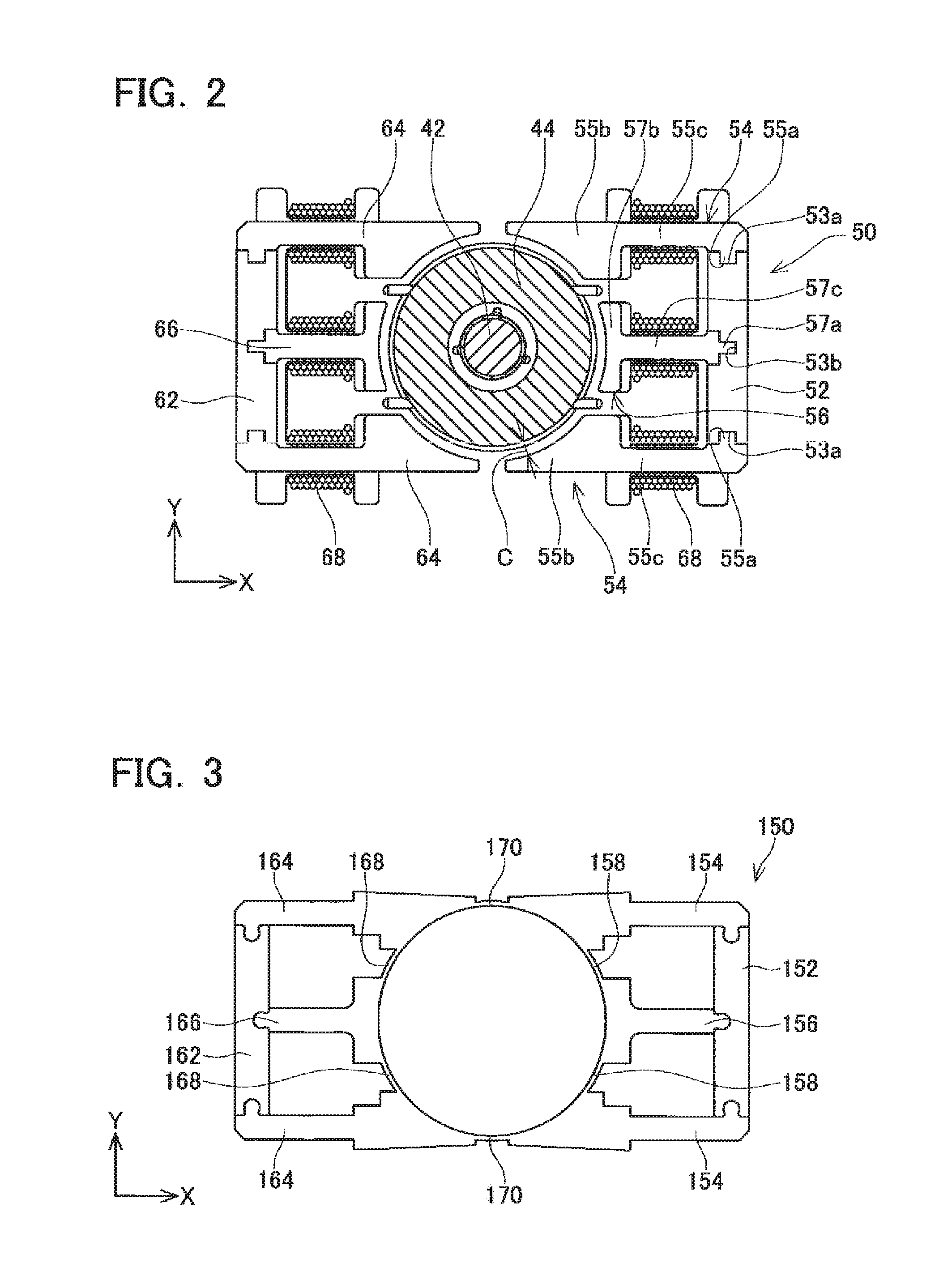
[0014]In one aspect of a brushless motor, a stator may comprise a first yoke and a second yoke opposing the first yoke, and a rotor may be disposed between the first yoke and the second yoke. In this case, three parallel teeth may be connected to each of the first yoke and the second yoke. According to such a configuration, the stator can be formed flat and the brushless motor can be downsized.

[0015]In an aspect of the brushless motor described above, the second tooth connected to each yoke may be connected in the second direction perpendicular to a rotor side surface of the yoke, and the first teeth connected to each yoke may be connected in the first direction parallel to the rotor side surface of the yoke. According to such a configuration, since the direction in which the first teeth are connected to the yoke and the direction in which the second tooth is connected to the yoke are perpendicular to each other, a connection between each tooth and the yoke can be favorably maintain...


PUM


Abstract

A brushless motor includes a rotor and a stator. The stator includes yokes and a plurality of teeth. Base ends of the teeth are connected to the yokes, and tip ends of the teeth oppose an outside surface of the rotor with an interval in between. The plurality of teeth include a pair of first teeth connected to both ends of the yokes and second teeth connected to centers of the yokes. The first teeth are connected to the yokes in a first direction, and the second teeth are connected to the yokes in a second direction which is different from the first direction.

Description

CROSS-REFERENCE TO RELATED APPLICATION[0001]This application claims priority to Japanese Patent Application No. 2011-223066 filed on Oct. 7, 2011, the contents of which are hereby incorporated by reference into the present application.TECHNICAL FIELD[0002]The present teachings relate to a brushless motor and an electric pump.DESCRIPTION OF RELATED ART[0003]Japanese Patent Application Publication No. 2006-340506 discloses a prior art brushless motor. The brushless motor includes a rotor and a stator disposed outside of the rotor. The stator includes two stator blocks having each stator block disposed on either side of the rotor. Each stator block includes a yoke and a plurality of teeth molded separately from the yoke. The plurality of teeth includes base ends connected to the yoke. Tip ends of the teeth oppose an outside surface of the rotor with intervals in between.BRIEF SUMMARY OF INVENTION[0004]With the brushless motor described in the above described art, a manufacturing error ...

Claims


Application Information

Patent Timeline
IPC IPC(8): H02K1/18F04D13/06
CPCH02K21/16H02K5/128H02K5/08H02K1/148H02K3/524
Inventor SUGIMOTO, ATSUSHI
Owner AISAN IND CO LTD
Why Eureka
Try Eureka