Method and device for detecting a critical hemodynamic event of a patient

a hemodynamic event and patient technology, applied in the field of detecting a critical physiological state of a patient, can solve the problems of regulation failure, critical patient state related to such regulation failure, and often not or recently noticed, and achieve the effect of improving patient safety

Inactive Publication Date: 2013-04-11
KONINKLIJKE PHILIPS ELECTRONICS NV
View PDF8 Cites 20 Cited by
  • Summary
  • Abstract
  • Description
  • Claims
  • Application Information

AI Technical Summary

Benefits of technology

[0005]It is an object of the invention to provide a method for detecting a critical hemodynamic event of the patient as described above that allows a permanent analysis of physiological parameters of the patient related to hemodynamic processes and an early detection of impending critical states thereof, so clinical staff, bystanders and / or the patient can be warned early in order to react appropriately. This leads to an improved patient safety in low acuity settings, like emergency waiting rooms, during patient transports, general ward situations, etc. Another object of the invention is to provide a corresponding device for detecting such a critical hemodynamic event.

Problems solved by technology

Hemodynamic regulation failures—which can cause serious injuries due to a fall of a fainting patient—are currently not detectable based on state of the art monitoring equipment and existing algorithm approaches.
Therefore critical patient states related to such regulation failures are often not or lately noticed by clinical staff in lower acuity settings, since patients are not or seldom monitored.
Root causes of regulation instabilities and regulation failures are dehydration, a developing infection, medication incompatibility, wrong drug dosages, etc.
The existing classical sensor portfolio, which was developed primarily for high acuity settings, is not well suited for continuous, reliable and comfortable patient monitoring in low acuity settings in terms of usability, robustness and comfort.
However, a regulation failure can happen in a few seconds.
Therefore, critical events or the onset of a patient de-compensation are lately noticed, which can result in suboptimal patient treatment, hospital acquired injuries, longer hospital stays and therefore increased costs.

Method used


Image

  • Method and device for detecting a critical hemodynamic event of a patient
  • Method and device for detecting a critical hemodynamic event of a patient
  • Method and device for detecting a critical hemodynamic event of a patient

Examples


Embodiment Construction

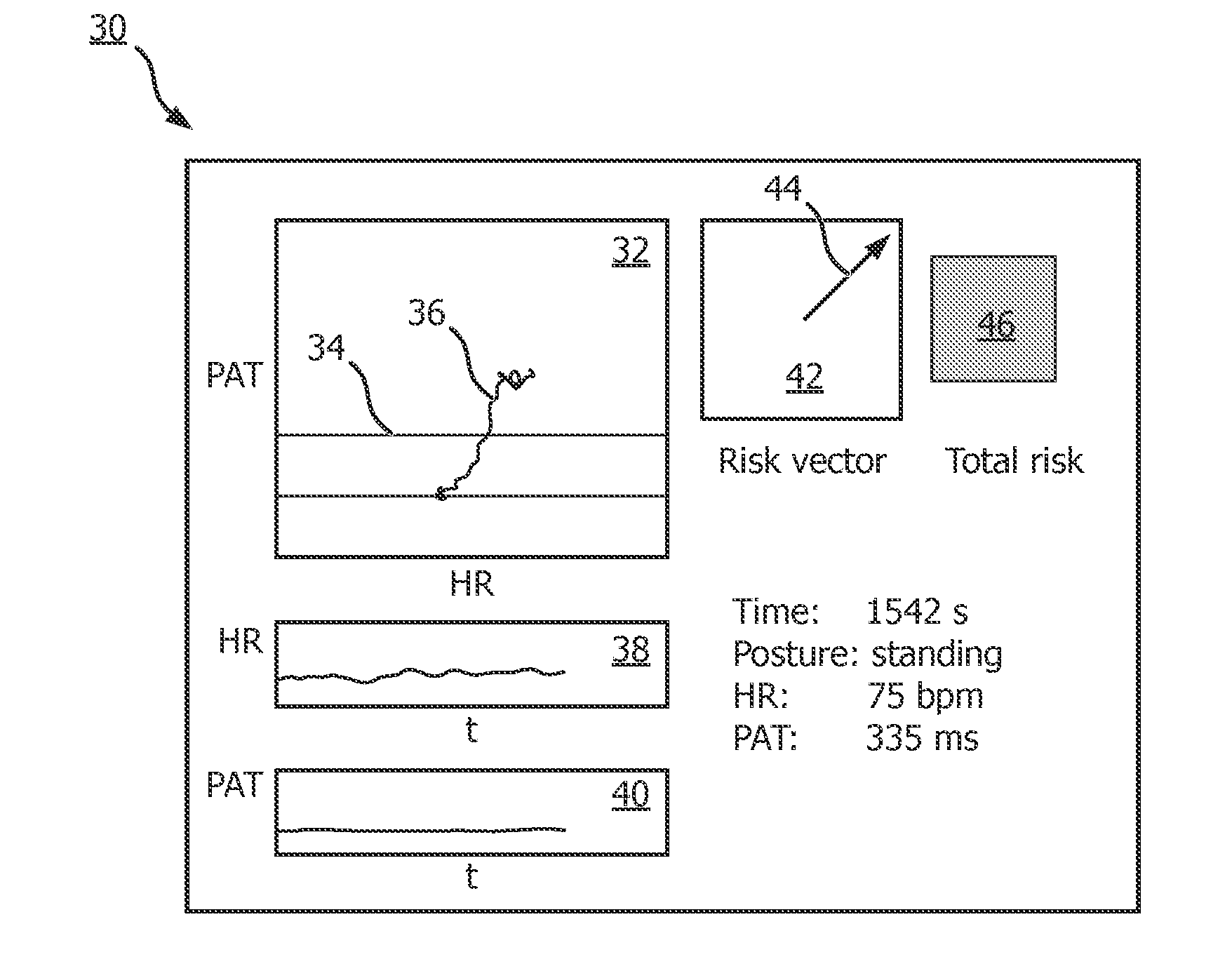
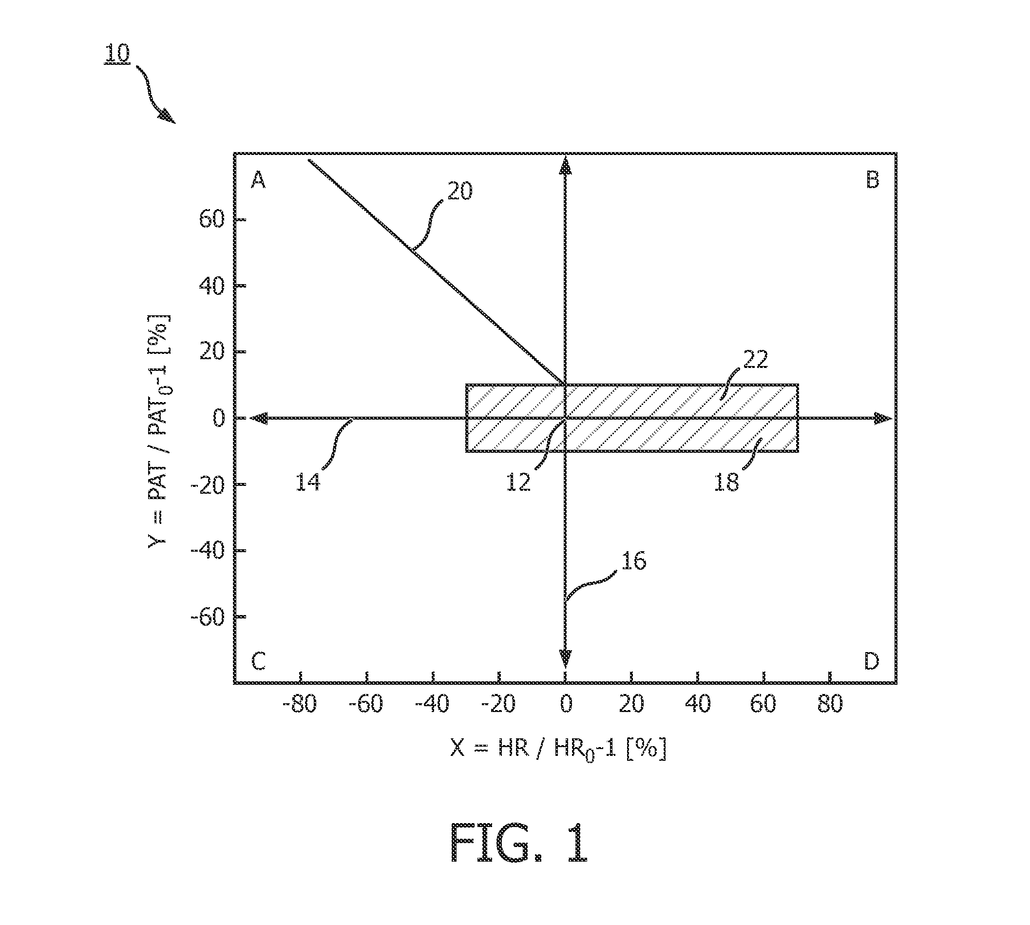
[0043]In the following a first embodiment of a method for detecting a critical hemodynamic event of a patient is described. In this method a set of values of physiological parameters of the patient is measured permanently to acquire sets of values related to different points of time t. The values represent the output of a plurality of sensors, including one sensor for measuring a value of the heart rate (HR) and another sensor for determining a value of the pulse arrival time (PAT). PAT can be measured as the time interval between the R-peak in the ECG and a feature of a measured signal related to a passing pulse in an artery at a certain body position using, for example, a PPG sensor or a piezoelectric sensor. For each point of time t, a set of two values is gained, namely one value for the heart rate (HR) and one for the pulse arrival time (PAT). As it will be laid out in the following, this combination of two physiological parameters can be used to derive a certain risk of the oc...


PUM


Abstract

The invention relates to a method and a device for detecting a critical physiological state of a patient, especially for detecting a critical hemodynamic event. A set of values of physiological parameters is measured, including the heart rate and the pulse arrival time. On the basis of these measurements, a risk assessment is performed including the allocation of a representation of the measured set of values as a vector in a vector space to a risk level representing the risk of the occurrence of a critical hemodynamic event.

Description

FIELD OF THE INVENTION[0001]The invention relates to the field of detecting a critical physiological state of a patient, especially for detecting an impending critical hemodynamic event. The invention further relates to a corresponding device provided to detect such a critical hemodynamic event.BACKGROUND OF THE INVENTION[0002]Patient safety in hospitals has attracted more and more attention in order to prevent medical errors and adverse health care events. There is a clear trend to improve patient safety that calls for better coverage of preventable injuries and death. In this context early detection of critical hemodynamic events, e.g. critical systolic blood pressure drops is still an unmet need in low acuity settings in hospitals as well as in home scenarios. Hemodynamic regulation failures—which can cause serious injuries due to a fall of a fainting patient—are currently not detectable based on state of the art monitoring equipment and existing algorithm approaches. Therefore c...

Claims


Application Information

Patent Timeline
Patent Type & Authority Applications(United States)
IPC IPC(8): A61B5/024A61B5/0245A61B5/0402A61B5/00
CPCA61B5/02028A61B5/02125A61B5/0245A61B5/0285A61B5/7275A61B5/743A61B5/024A61B5/02416A61B5/0402A61B5/6802A61B5/742A61B5/0004G16H40/67G16H50/20A61B5/318
Inventor MUHLSTEFF, JENSMORREN, GEERT GUY GEORGESMEYER, CHRISTIAN
Owner KONINKLIJKE PHILIPS ELECTRONICS NV
Why Eureka
Try Eureka