Battery-powered vacuum cleaner
- Summary
- Abstract
- Description
- Claims
- Application Information
AI Technical Summary
Benefits of technology
Problems solved by technology
Method used
Image
Examples
first embodiment
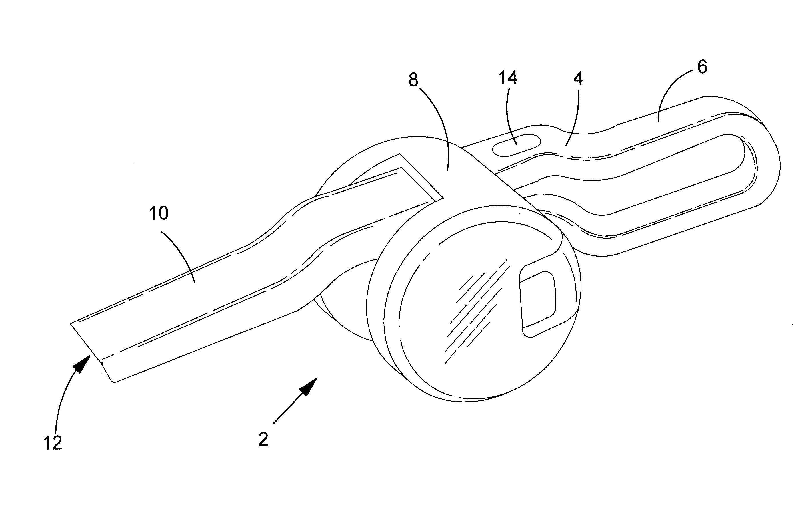
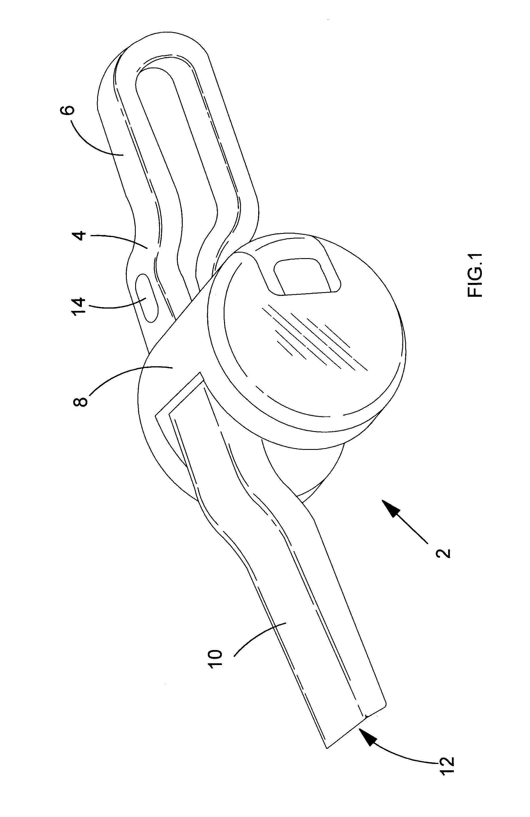
[0077]Referring to FIG. 1, there is shown first embodiment of a hand-held vacuum cleaner 2 comprising a main body 4, a handle 6 connected to the main body, a cyclonic separation apparatus 8 mounted transverse across the main body, and a dirty air duct 10 with a dirty air inlet 12 at one end. The vacuum cleaner comprises a motor coupled to a fan for generating air flow through the vacuum cleaner and rechargeable cells (not shown) to energise the motor when electrically coupled by an on / off switch 14.
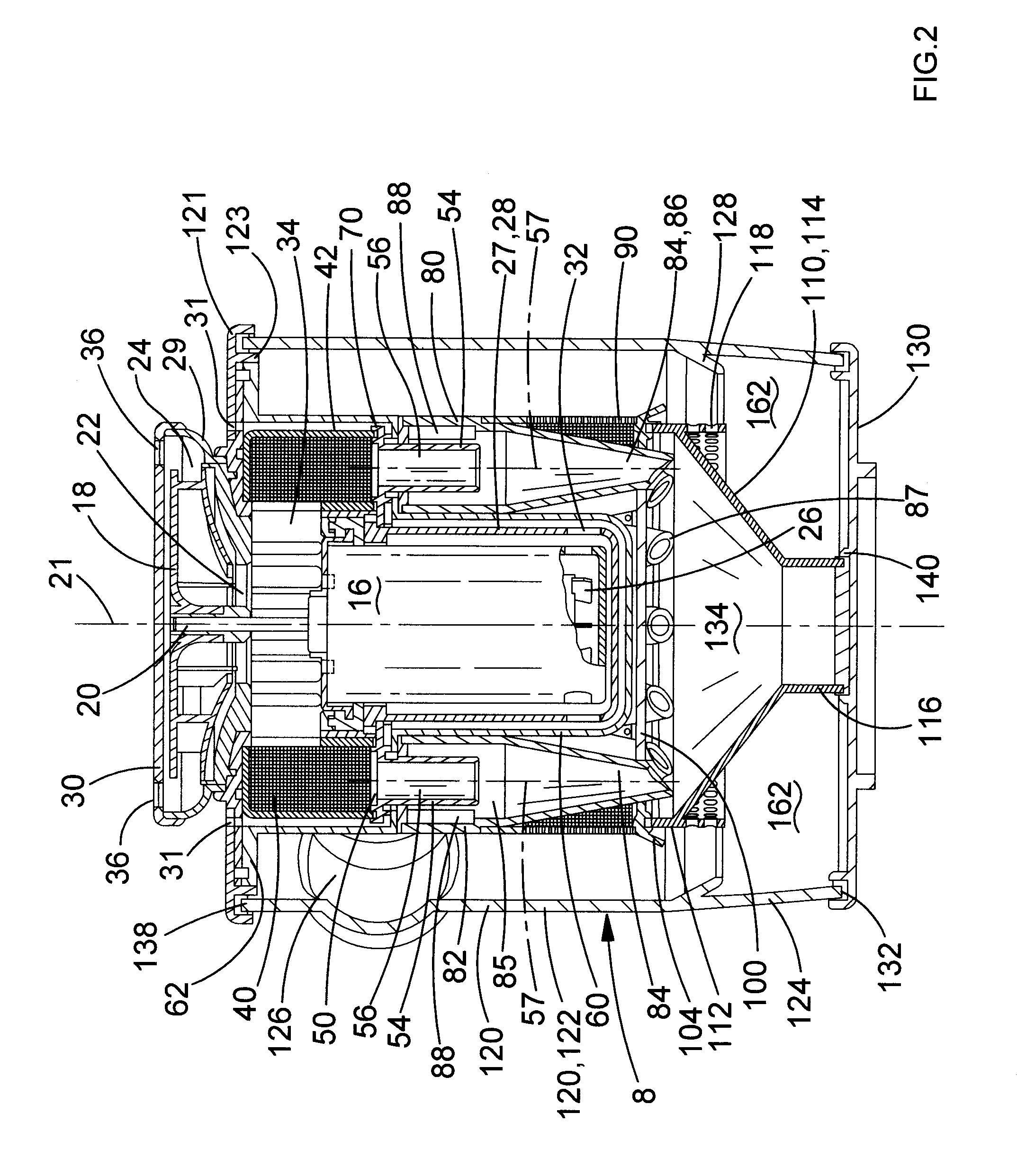
[0078]Referring to FIGS. 2 to 8, there is shown an arrangement comprising the motor 16, the fan 18 and the cyclonic separation apparatus 8. The motor has a drive shaft 20 with a central axis 21. The fan is a centrifugal fan 18 with an axial input 22 facing the motor and a tangential output 24. The fan has a diameter of 68 mm. The fan is mounted upon the drive shaft at the top of the motor. In use, the motor drives the fan to generate air flow through the cyclonic separation apparatus, as ...
second embodiment
[0115]Referring to FIGS. 10 and 11, there is shown a hand-held vacuum cleaner 202 comprising a main body 204 with a main axis 205, a handle 206, a cyclonic separation apparatus 208 mounted transverse to the main axis of the main body, and a dirty air duct 210 with a dirty air inlet 212 at one end. The vacuum cleaner comprises a motor 216 coupled to a fan for generating air flow through the vacuum cleaner and rechargeable cells 217 to energise the motor when electrically coupled by an on / off switch 214.
[0116]Referring to FIGS. 12 to 16, there is shown an arrangement comprising the motor 216, the rechargeable cells 217, the fan 218, a pre-fan filter 240, a cyclonic separation apparatus outlet duct 260 and the cyclonic separation apparatus 208.
[0117]The motor has a drive shaft 220 with a longitudinal central axis 221. The fan is a centrifugal fan 218 with an axial input 222 facing away from the motor and a tangential output 224. The fan has a diameter of 68 mm. The fan is mounted upon ...
third embodiment
[0152]Referring to FIG. 23, there is shown hand-held vacuum cleaner 402 comprising a main body 404 with a handle 406, a cyclonic separation apparatus 408 mounted to the main body, and a dirty air duct 410 with a dirty air inlet 412 at one end. The vacuum cleaner comprises a motor coupled to a fan for generating air flow through the vacuum cleaner and rechargeable cells to energise the motor when electrically coupled by an on / off switch 414.
[0153]Referring to FIGS. 24 to 27, there is shown in more detail the motor 416, the rechargeable cells 417, the fan 418, a pre-fan filter 440, a cyclonic separation apparatus outlet duct 460 and the cyclonic separation apparatus 408.
[0154]The motor has a drive shaft 420. The fan 418 is mounted upon the drive shaft at the top of the motor. The fan has a diameter of approximately 68 mm. The cells 417 are arranged about the motor 416. In use, the motor drives the fan to generate air flow through the cyclonic separation apparatus, as will be described...
PUM
 Abstract
Description
Claims
Application Information
 - R&D
- Intellectual Property
- Life Sciences
- Materials
- Tech Scout
- Unparalleled Data Quality
- Higher Quality Content
- 60% Fewer Hallucinations
Browse by: Latest US Patents, China's latest patents, Technical Efficacy Thesaurus, Application Domain, Technology Topic, Popular Technical Reports.
© 2025 PatSnap. All rights reserved.Legal|Privacy policy|Modern Slavery Act Transparency Statement|Sitemap|About US| Contact US: help@patsnap.com


