
Folding vehicle having a chassis that functions as a protective, carry-on casing

a technology of carrying-on casings and folding vehicles, which is applied in the direction of frictional roller based transmission, steering devices, cycle equipments, etc., can solve the problems of limited use of bicycles, limited protection of users from chain sets, and inability to accept traditional bicycles in all mass transit systems

Inactive Publication Date: 2013-04-18
MDM PRODIVITY
View PDF0 Cites 6 Cited by
  • Summary
  • Abstract
  • Description
  • Claims
  • Application Information

AI Technical Summary

Benefits of technology

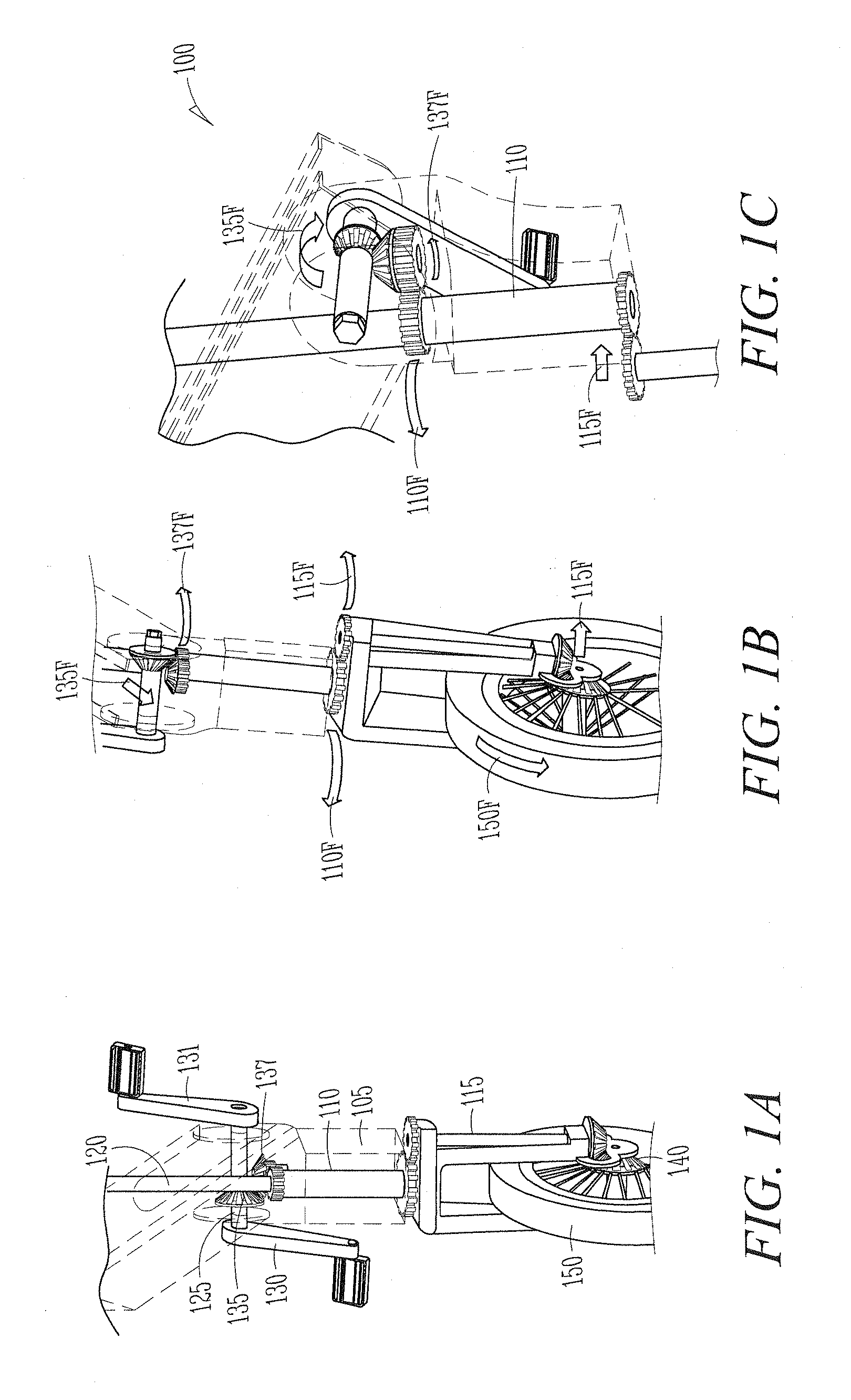
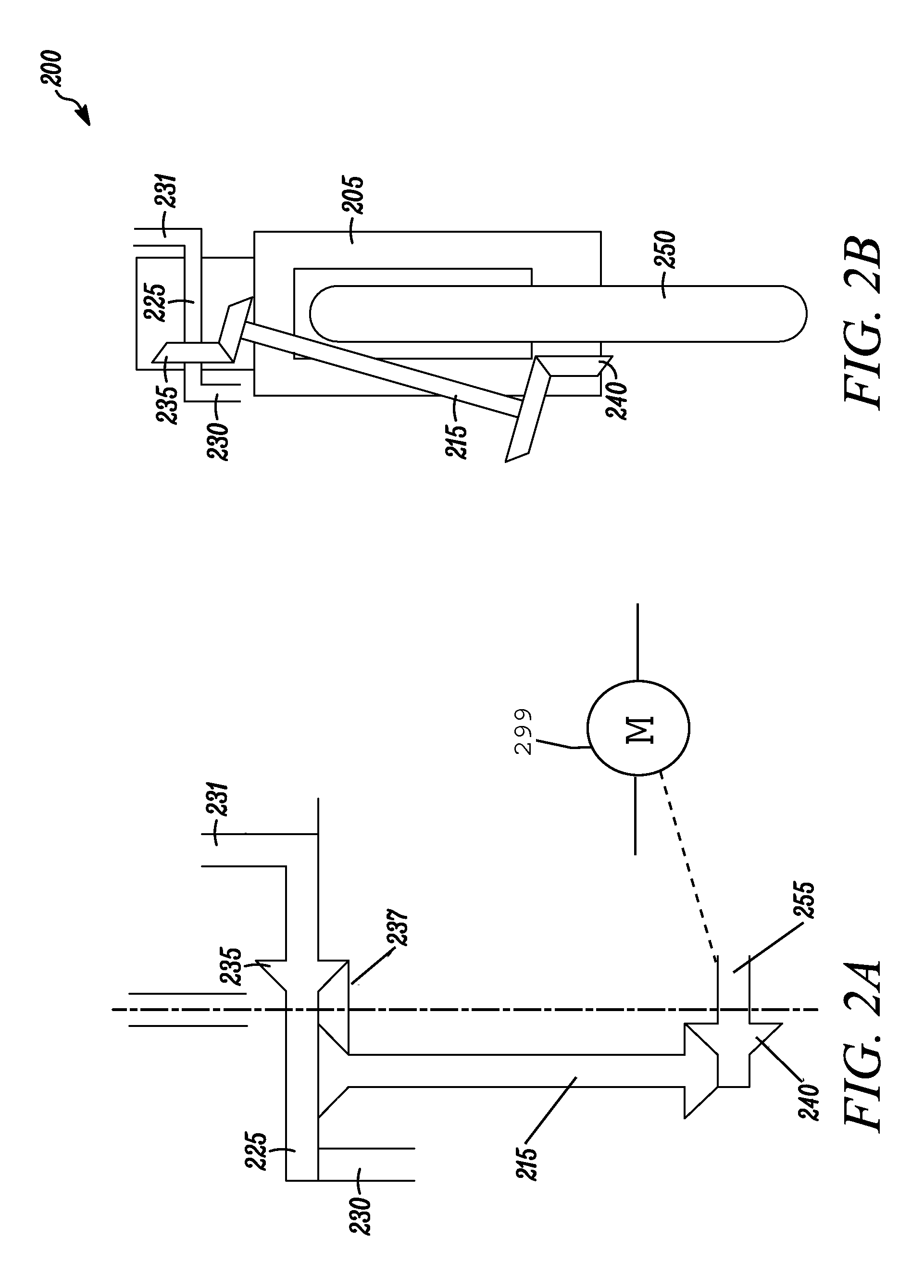
[0010]In some embodiments, for example, the teachings are directed to a compact, combination drive-and-steering unit for a vehicle, the unit having a shared rotational space comprising a portion of a drive assembly and a portion of a steering assembly. The drive assembly can include a crankshaft having a crank axis that rotates in a fixed position relative to a chassis of a vehicle powered by the crankshaft. The crankshaft can be in an operable communication with a spool-shaft having a drive axis, the spool-shaft in an operable communication with a drive member. The drive member can be in an operable communication with a wheel assembly having a wheel, the drive assembly transferring a power from the crankshaft to drive the wheel. The steering assembly can include a strut in an operable communication with the wheel assembly, a steering axle in an operable communication with the strut, and a steering member in an operable communication with the steering axle. The steering axle can have a steering axis that is concentric to the drive axis of the spoolshaft in the shared rotational space, the spoolshaft circumscribing at least a portion of the steering axle. The steering axle can rotate freely, or substantially freely, within the spoolshaft, such that the crankshaft rotates in the fixed position independent, or substantially independent, of a rotation of the steering axle. The shared rotational space creates a compact, combination drive-and-steering unit for the vehicle.
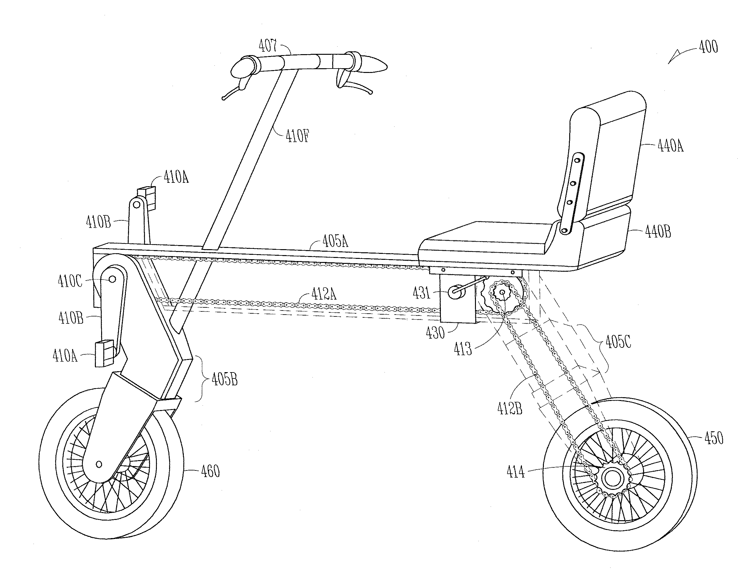
[0025]Likewise, a bicycle can have the drive-and-chassis unit. As such, the teachings are also directed to a compact, carry-on bicycle with an enclosed, drive assembly. In these embodiments, the bicycle can include a shared chassis space comprising (i) at least a portion of a chassis assembly that encloses (ii) at least a substantial portion of a drive assembly, as well as a folding chassis including (iii) a rotatably-lockable front strut supporting a front wheel assembly having a front wheel, and (iv) a rotatably-lockable rear strut supporting a rear wheel assembly having a rear wheel. The drive assembly can include a pair of pedals attached to a pair of crankarms, the pair of crankarms attached to a crankshaft. The crankshaft can have a crank axis that rotates under a pedal power in a fixed position in the chassis, the crankshaft in an operable communication with a spool-shaft having a drive axis. The spool-shaft can be in an operable communication with a drive member, and the drive member in an operable communication with the front wheel, the drive assembly transferring the pedal power from the crankshaft to drive the front wheel. The portion of the chassis assembly can function as a protective casing for the substantial portion of the drive assembly, the substantial portion of the drive assembly comprising the crankshaft and at least a substantial portion of the drive member. The drive member can have a fixably rotatable pivot point corresponding to a fixably rotatable joint in the chassis assembly for a re-direction of the pedal power from the crankshaft to the pivot point and from the pivot point to the wheel. The front strut can have a proximal end and a distal end, the proximal end of the front strut attaching to the chassis at a rotatably-lockable front strut pivot. The rear strut can have a proximal end and a distal end, the proximal end of the rear strut attaching to the chassis at a rotatably-lockable rear strut pivot. And, the shared chassis space can create a compact, combination drive-and-steering unit for the pedal-powered vehicle.

Problems solved by technology

Other vehicles still create this problem, as their design inherently exposes the user to such lubricants.
Bicycles, for example, are almost exclusively driven by chain sets, and the conventional lightweight construction of bicycles limit the extent to which the user can be protected from the chain sets and still maintain the desired weight and performance of the bicycle.
Moreover, the use of bicycles is limited by the ability to carry and store the bicycles.
For example, a user of mass transit, such as trains, buses, taxi's, and even airplanes and boats, needs to carry-on the bicycle in some way, and not all mass transit systems can accept traditional bicycles.
Folding bicycles exist, but they still remain greasy, large, and heavy, as well as introduce shear and pinch points that can be dangerous to the user.

Method used


Image

  • Folding vehicle having a chassis that functions as a protective, carry-on casing
  • Folding vehicle having a chassis that functions as a protective, carry-on casing
  • Folding vehicle having a chassis that functions as a protective, carry-on casing

Examples


example 1

[0072]In some embodiments, a vehicle can be manufactured from roughly a 36″×36″ piece of sheet steel or aluminum. It should be appreciated that alternate chassis materials can include plastic, fiberglass, carbon fiber, or other metal alloys, resins, or combinations thereof.

[0073]The vehicle can be a bicycle, for example. Depending on the height of the C-channel sides, the sheet is marked, cut and bent into an inverted C-channel with roughly a 6″ wide back and 6″ to 12″ high sides to the C-channel. The top of the channel can be bent to include a lip on each outer side of the channel to accommodate a sliding seat that is lockable in position for varying rider sizes. Holes are stamped or drilled into the C-channel to accommodate axles and pivot points, as well as any other points of attachment. The axles for mounting the struts, for example, are attached to the C-channel. The wheels are positioned in tandem using uni-struts, as opposed to forks, to allow for a complementary positioning...

example 2

[0078]The vehicle can be manufactured and purchased as a kit that provides flexibility the type of vehicle, such that the vehicle can be transformed for additional uses. For example, the kit can comprise (i) three struts; (ii) a C-channel, (iii) a drive-and-steering unit; (iv) a drive-and-chassis unit; (v) a collapsible steering member; (vi) a collapsible seat; (v) a hub-motor; (vi) a battery set for the hub motor; (vii) a case for the battery set; (viii) a multi-gear hub; (ix) a utility box or deck for transporting items; (x) a tandem extension for an additional passenger; (xii) a harness for a hands-free carrying of the vehicle, or some combination thereof.

[0079]The kits could also come with instructions for assembly of the vehicles into various transformation modes. And, optionally, the kits could come with software, or other digital media, that may facilitate teaching a user how to operate and construct the systems.

[0080]The kits can be offered to provide much additional utility...


PUM


Abstract

A folding vehicle having a chassis that functions as a protective, carry-on casing is provided. The vehicle has a chassis with a center member, a rotatably-lockable front strut, a rotatably-lockable rear strut, and two pivot points for converting the vehicle from an operational state to a collapsed state; and, a drive member with a crankshaft. The crankshaft and the rotatably-lockable front strut pivot share a central axis of rotation; and, the releasably-lockable front strut and the releasably-lockable rear strut are configured to fold into a complementary relationship in the interior of the channel in the collapsed state. The channel functions as a protective, carry-on case for the folding vehicle in the collapsed state.

Description

CROSS-REFERENCE TO RELATED APPLICATIONS[0001]This application is a continuation of U.S. patent application Ser. No. 13 / 229,646, filed on Sep. 9, 2011, which is herein incorporated by reference in its entirety.BACKGROUND[0002]1. Field of the Invention[0003]The teachings provided herein are generally directed to compact vehicle drive mechanisms that can be used in the design of a foldable, carry-on vehicle.[0004]2. Description of the Related Art[0005]Vehicles used for transportation generally all expose the user to some transfer of mechanical lubricants from the vehicle to the user, such as oil and grease, for example. Automobiles have generally done a good job of reducing the user's exposure to such lubricants by enclosing areas of the automobile that introduce this problem to the user. Other vehicles still create this problem, as their design inherently exposes the user to such lubricants.[0006]Bicycles, for example, are almost exclusively driven by chain sets, and the conventional ...

Claims


Application Information

Patent Timeline
Patent Type & Authority Applications(United States)
IPC IPC(8): B62K15/00B62M6/55B62M1/36
CPCB62K15/008B62M1/36B62K15/00B62M1/12B62K3/005B62M6/55
Inventor MOLDESTAD, JON P.
Owner MDM PRODIVITY
Learn More