Heat sink and a method for making the same

Inactive Publication Date: 2013-06-27
HUANG TSUNG HSIEN
View PDF6 Cites 1 Cited by
  • Summary
  • Abstract
  • Description
  • Claims
  • Application Information

AI Technical Summary

Benefits of technology

[0016]1. When the bent flakes with the gaps are disposed at the bottom end of each fin unit of the fin set, the holding members of the radiating seat are deformed by the punching of the punching mold so as to firmly hold at least one side of each of the gaps of the bent flakes on the fin set. Accordingly, the radiating seat and the fin set could be combined rapidly. Moreover, the present invention reduces the distance between every fin unit of the fin set so as to promote the number of the fin units of the fin set, thereby enhancing the heat dispersing effect. Preferably, the combination of the radiating seat and the fin set is simplified.
[0017]2. The method of the present invention comprises procedures of drawing-extrusion, cutting, ripping, inserting, and punching to complete the combination of the radiating seat and the fin set. An extruded body that is proceeded with drawing-extrusion forming has at least one set of elongated strips at an upper end thereof. Thence, the extruded body is cut into separate sub rippled bodies. Thereafter, the elongated strips on the sub extruded body are ripped with intervals so as to form a plurality of separate sets of holding members on the elongated strips. The bent flakes with gaps are disposed at the bottom end of each fin unit of the fin set. When the fin set is inserted into the radiating seat, the gaps of the bent flakes are matched with the holding members. Accordingly, the holding members are punched by the punching molds for downwardly deforming so

Problems solved by technology

However, the radiating seat is thick, which thence consumes more materials to manufacture.
The conventional heat sink is accordingly bulky and incurs high manufacturing

Method used


Image

  • Heat sink and a method for making the same
  • Heat sink and a method for making the same
  • Heat sink and a method for making the same

Examples


Example

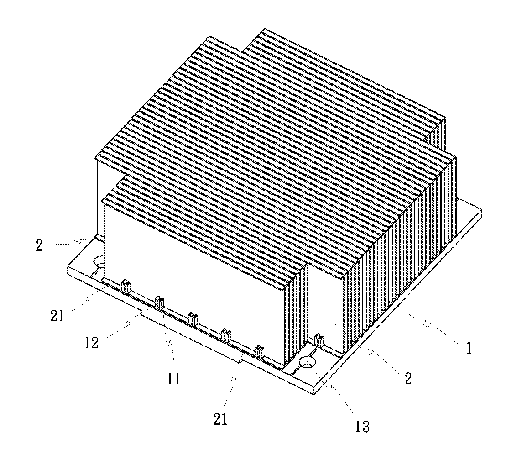
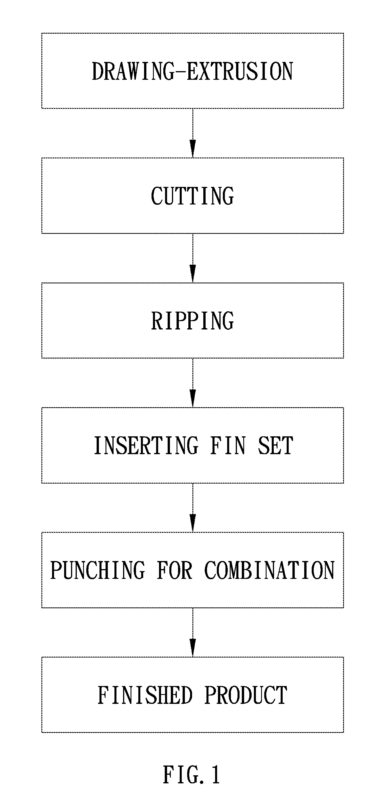
[0057]FIG. 1 shows a first preferred embodiment of the present invention. A method for making a heat sink comprises procedures of drawing-extrusion, cutting, ripping, inserting, and punching to complete a combination of a radiating seat 1 and a fin set 2.

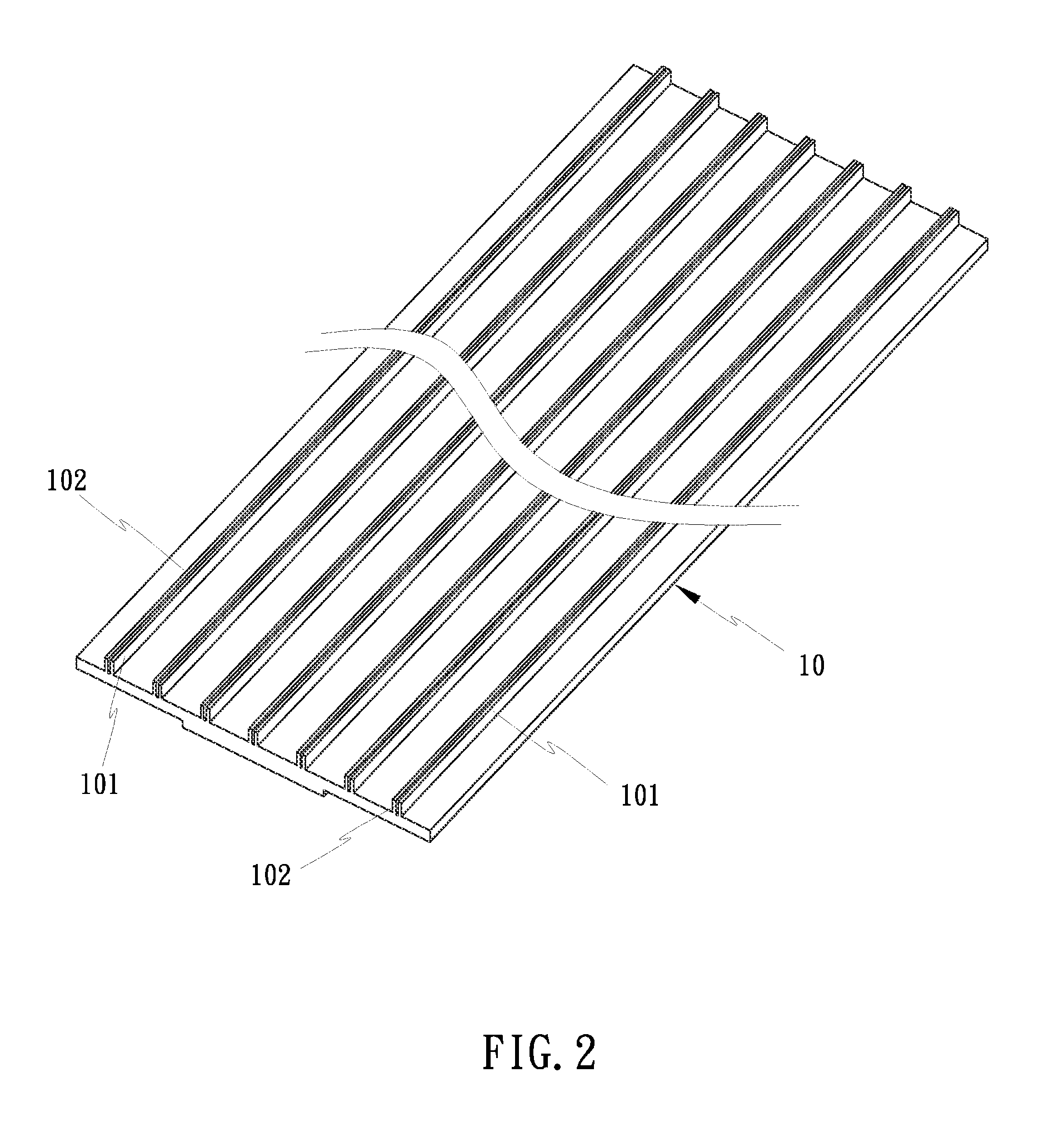
[0058]Drawing-extrusion: shape aluminum or copper metal into a long extruded body 10 (as shown in FIG. 2) with a plate shape by a drawing-extrusion forming method, and form at least one set of elongated strips 101,102 symmetrically arranged at an upper end thereof. (The extruded body 10 could alternatively form one elongated strip 101 or 102.) The extruded body 10 is proceeded with drawing-extrusion for shaping into a sheet.

[0059]Cutting: cut the extruded body 10 into separate sub rippled bodies 1a (as shown in FIG. 3) in accordance with the practical needs. Wherein, each sub extruded body 1a is correspondingly provided with at least one set of symmetrical elongated strips 101,102. Thence, each sub extruded body 1a is served as a mo...


PUM

PropertyMeasurementUnit
Timeaaaaaaaaaa

Abstract

A heat sink and a method for making the same include steps of drawing-extrusion, cutting, ripping, inserting, and punching. By the step of drawing-extrusion, an extruded body is extruded and on an upper end thereof forms at least one set of elongated strips. The extruded body is cut into sub rippled bodies, and the elongated strips are ripped at intervals for forming separate sets of holding members. A fin set forms bent flakes with gaps at a bottom end of each fin unit thereof for combining with a radiating seat. Punched by punching molds, the holding members deform for firmly holding the bent flakes on each fin unit of the fin set, thereby achieving a complete combination of the radiating seat and the fin set. Accordingly, the radiating seat is lighter, which saves more materials and reduces manufacturing costs.

Description

CROSS REFERENCE TO RELATED APPLICATIONS[0001]This application is based upon and claims the benefit of priority from the prior China Patent Application No. 201110433443.6, filed on Dec. 22, 2011, the entire contents of which are incorporated herein by reference.BACKGROUND OF THE INVENTION[0002](a) Field of the Invention[0003]The present invention relates to a heat sink and a method for making the same by substantially providing a sub extruded body whose top is ripped to form several separate sets of holding members that are symmetrically arranged; when the holding members are punched, they deform for firmly holding a fin set; the present invention conduces to a rapid combination of a radiating seat and the fin set.[0004](b) Description of the Prior Art[0005]A conventional aluminum (copper) extruded heat sink comprises a radiating seat and a fin set that are integrally structured. This heat sink provides a concise structure. However, the radiating seat is thick, which thence consumes ...

Claims


Application Information

Patent Timeline
IPC IPC(8): F28F7/00B23P15/26
CPCG06F1/20Y10T29/4935B23P2700/10F28F3/06F28D15/0275F28F1/32F28D2021/0029F28F2255/08F28F2275/122F28F2215/04H01L23/3672H01L21/4878H01L21/4882H01L2924/0002H01L23/427H01L2924/00Y02P70/50H01L23/34H05K7/20
Inventor HUANG, TSUNG-HSIEN
Owner HUANG TSUNG HSIEN
Why Eureka
Try Eureka