Telephoto lens unit

a technology of telephoto lens and lens body, which is applied in the field of telephoto lens units, can solve the problems of high cost unbalance in the center of gravity, and the inability of interchangeable telephoto lens to function as terrestrial telescope, and achieve the effect of different magnification, long distance from the image-most surface of the telephoto lens to the image formation plane thereo

Inactive Publication Date: 2013-04-18
KOWA CO LTD
View PDF2 Cites 33 Cited by
  • Summary
  • Abstract
  • Description
  • Claims
  • Application Information

AI Technical Summary

Benefits of technology

[0020]In the present invention, the distance from the image-most surface of the telephoto lens to the image formation plane thereof can be kept long. The rear lens barrel section of the telephoto lens unit can be disconnected and, instead thereof, a converter lens unit having a different magnification can be connected. Therefore, by connecting the telephoto lens unit to the camera body a desired telescopic image of a subject can be photographed with a different focal distance (i.e., a different magnification).
[0021]Instead of the disconnected rear lens barrel section, an image-erecting means and an eyepiece unit are also connected to enable the telephoto lens to be used as a terrestrial telescope.

Problems solved by technology

This allows a desired telescopic image to be taken with comfortable operability, but the drawback of an interchangeable telephoto lens having excellent optical performance is its high cost.
Also, an interchangeable telephoto lens does not function as a terrestrial telescope because an erecting prism having a sufficient field of view cannot be inserted in the rear portion of the interchangeable lens.
This causes unbalance to occur in the center of gravity including a camera and makes it difficult to use.
However, the system, being inherently a telescope, does not have components such as an AF and aperture, and is inferior to an interchangeable lens in terms of photographic performance and operability.

Method used


Image

  • Telephoto lens unit
  • Telephoto lens unit
  • Telephoto lens unit

Examples


embodiments

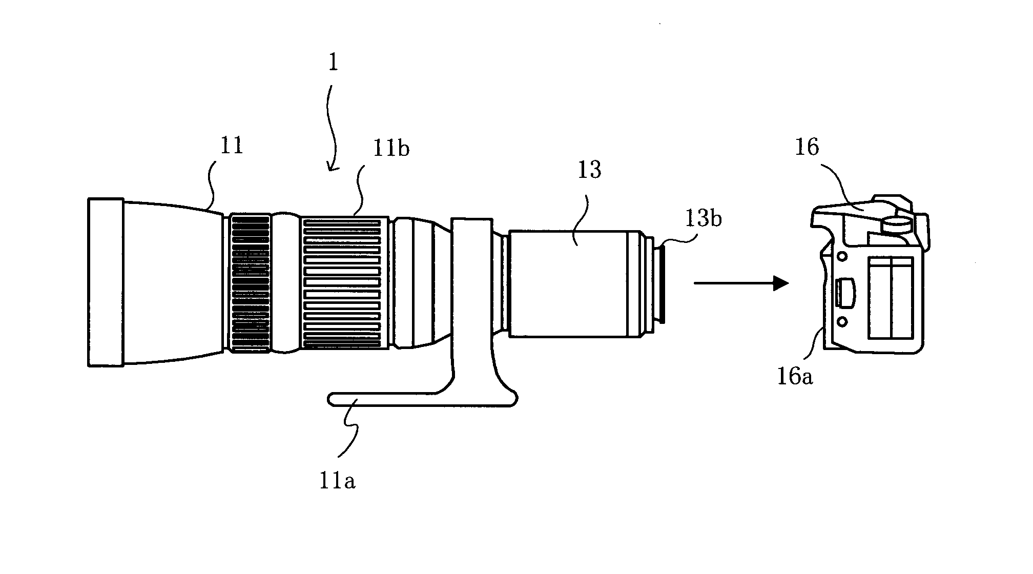
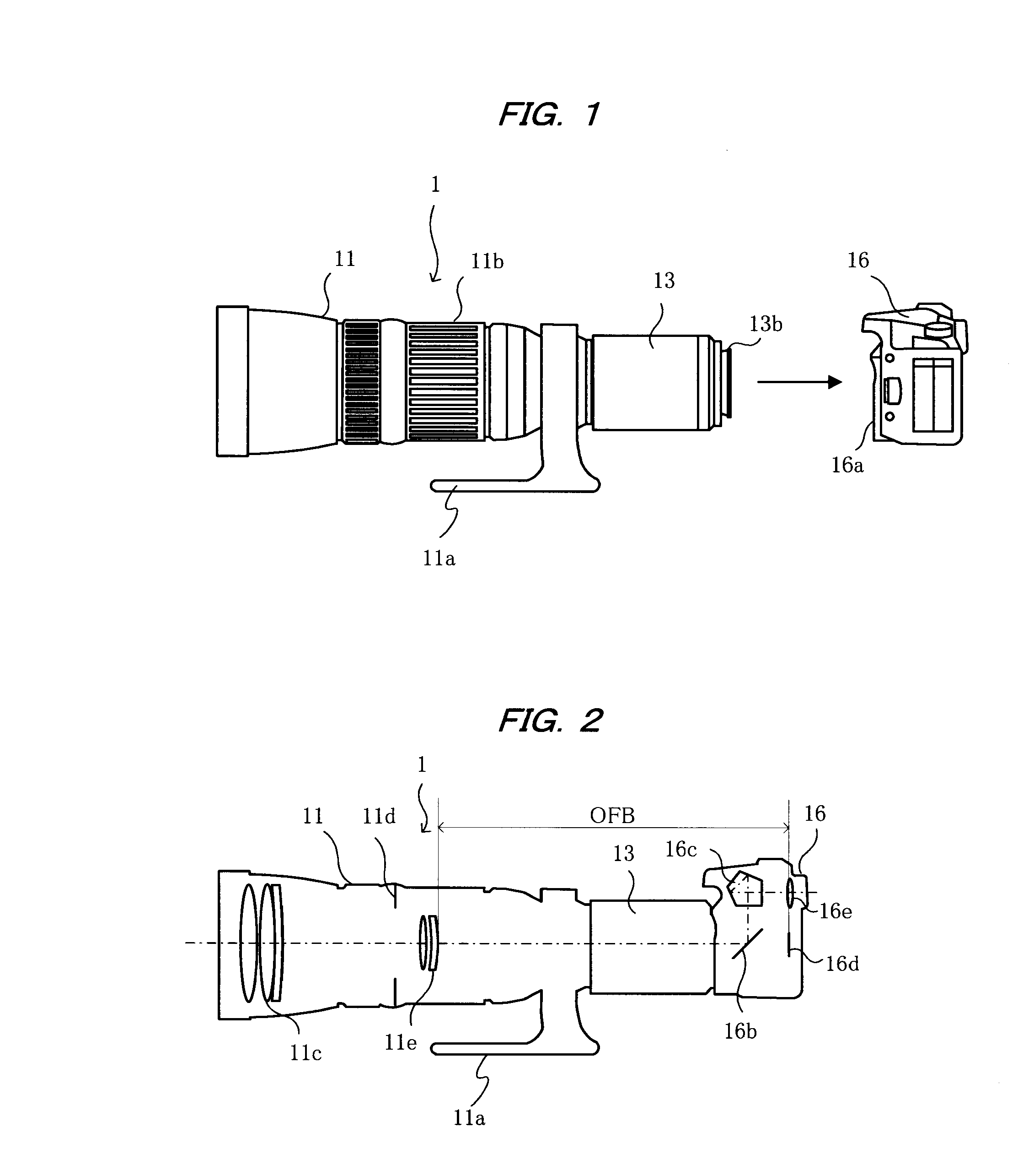
[0030]FIG. 1 shows an embodiment of the present invention in which a telephoto lens unit 1 is disconnected from a camera body 16 that is configured as a single lens reflex camera; and FIG. 2 shows the internal optical system of the telephoto lens unit 1 in a state when mounted on the camera body 16.

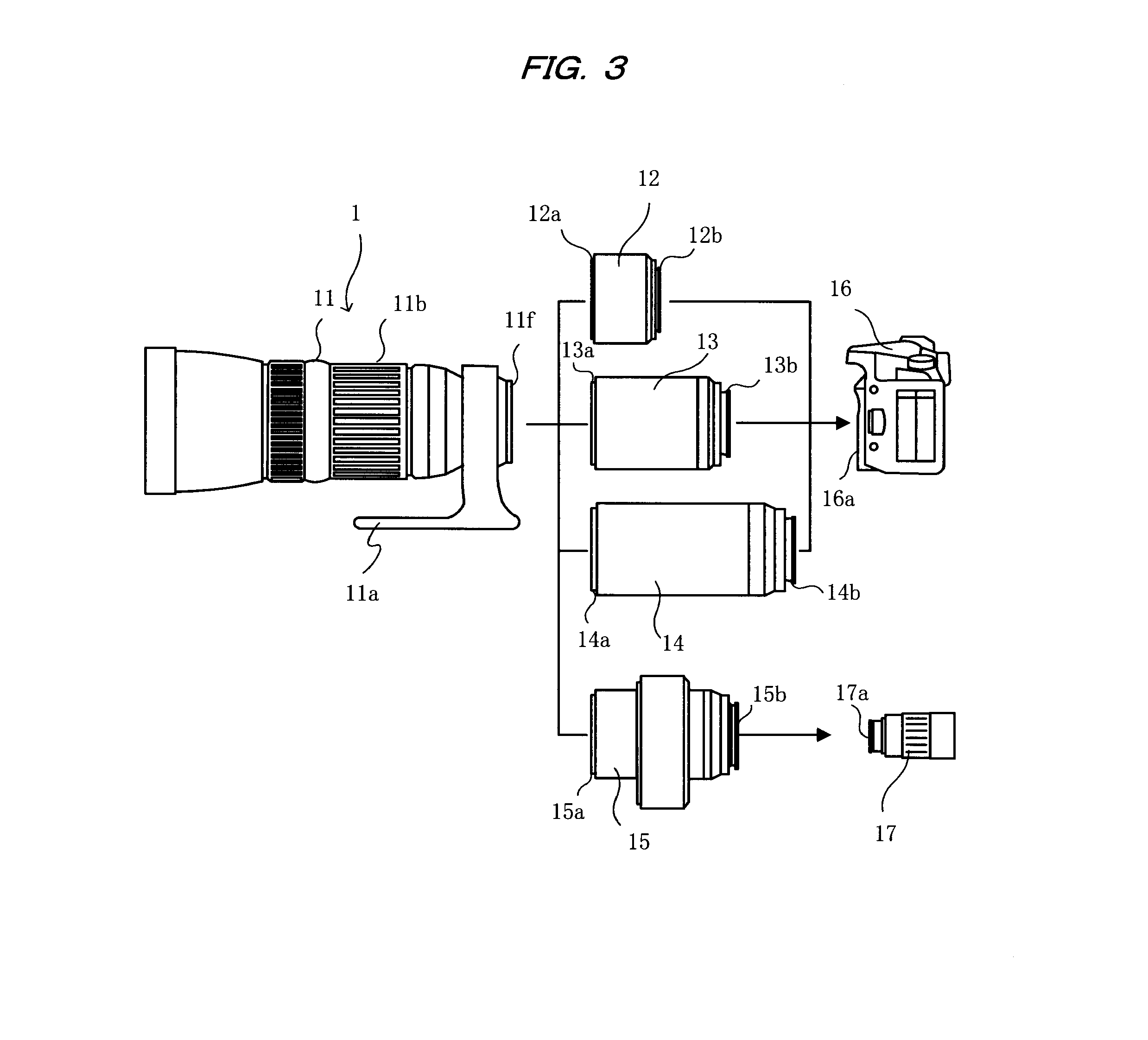
[0031]The telephoto lens unit 1 is composed of a front lens barrel section 11 (main unit of the telephoto lens unit) that supports a telephoto lens, with the subject side (left side in FIG. 1) being defined as the front, and a rear lens barrel section 13. The front lens barrel section 11 and the rear lens barrel section 13 can be disconnected as later described, and are mutually detachable.

[0032]A tripod seating 11a is attached to the telephoto lens unit 1, and the tripod seating 11a is attached to a tripod. This allows the telephoto lens unit 1 to be stably disposed in a predetermined position.

[0033]An objective lens system 11c, an aperture 11d, and a focus lens 11e are supported inside ...


PUM


Abstract

A telephoto lens unit (1) having a lens barrel that supports a telephoto lens and capable of being mounted on and dismounted from a camera body (16) comprises a front lens barrel section (11) that supports the telephoto lens with the subject side defined as the front, and a rear lens barrel section (13) that can be mounted on and dismounted from the front lens barrel section. The distance from the image-most surface of the telephoto lens to the image formation plane of the telephoto lens is kept sufficiently long. Converter lens units (12, 14) for elongating or shortening the focal distance are mounted on the front lens barrel section (11) instead of the rear lens barrel section (13) to provide interchangeable telephoto lenses for a camera having different focal lengths. Also, an erecting prism unit (15) and an eyepiece unit (17) can be connected instead of the rear lens barrel section to enable the telephoto lens to function as a terrestrial telescope.

Description

TECHNICAL FIELD[0001]The present invention relates to a telephoto lens unit capable of being used as an interchangeable telephoto lens for a camera and used as a terrestrial telescope.BACKGROUND ART[0002]When telephotography is to be performed using a camera, a lens unit having a mount compatible with each manufacturer must be mounted, such a lens unit being referred to as a so-called interchangeable lens in a single lens reflex camera. Alternatively, as other means, a camera is attached to a terrestrial telescope via a camera adapter to perform telephotography. There is also a photography method referred to as so-called direct-focus photography performed via a mount adapter on an astronomical telescope. Each approach has advantages and disadvantages.[0003]In the case in which an interchangeable lens is used, it is possible to perform an auto focus (AF) or control the aperture from a camera unit, and there are also configurations having a zoom function. This allows a desired telesco...

Claims


Application Information

Patent Timeline
Patent Type & Authority Applications(United States)
IPC IPC(8): G02B13/02
CPCG02B7/14G03B17/14G02B13/02G03B17/565G03B17/48
Inventor OGUCHI, YASUNARI
Owner KOWA CO LTD
Why Eureka
Try Eureka