Power supply device

a power supply device and power supply technology, applied in the direction of coupling device connections, basic electric elements, electrical apparatus casings/cabinets/drawers, etc., can solve the problem that users also need a larger storage space, and achieve the effect of convenient operation and storag

Inactive Publication Date: 2013-04-18
ASUSTEK COMPUTER INC
View PDF7 Cites 19 Cited by
  • Summary
  • Abstract
  • Description
  • Claims
  • Application Information

AI Technical Summary

Benefits of technology

[0008]The present disclosure is to provide a power supply device that can perform multiple functions, and ...

Problems solved by technology

Thus, the user also needs a larger space f...

Method used


Image

  • Power supply device
  • Power supply device
  • Power supply device

Examples


Embodiment Construction

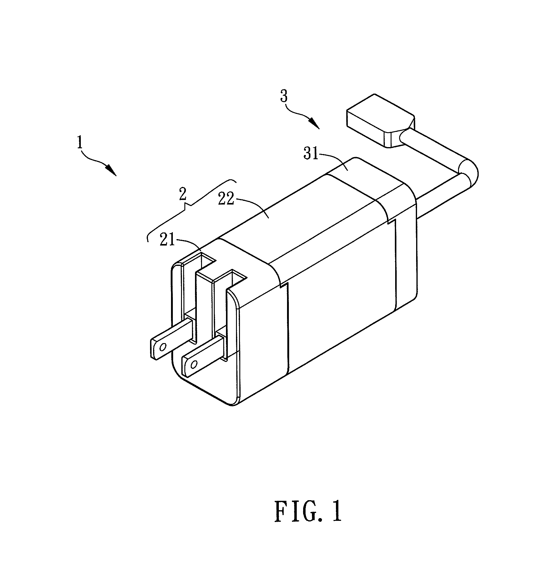
[0025]FIG. 1 is a schematic diagram showing a power supply device 1 according to an embodiment of the present disclosure. The power supply device 1 comprises a power input module 2 and a power functional module 3. The appearance of the power supply device 1 is rectangular for example. Of course, the appearance of the power supply device 1 of this disclosure is not limited to this, and it may be any shape that is easily held and operated, such as cylinder, square or the likes.

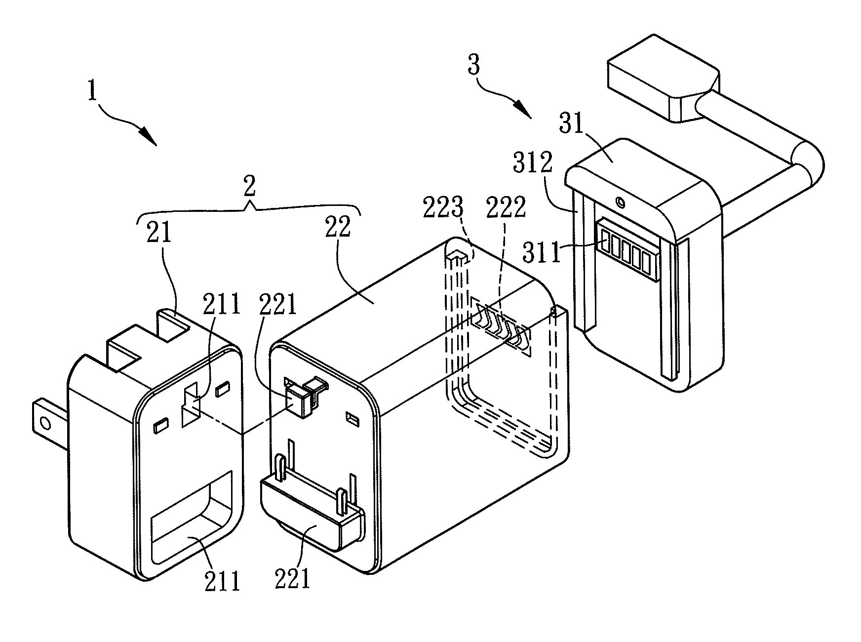
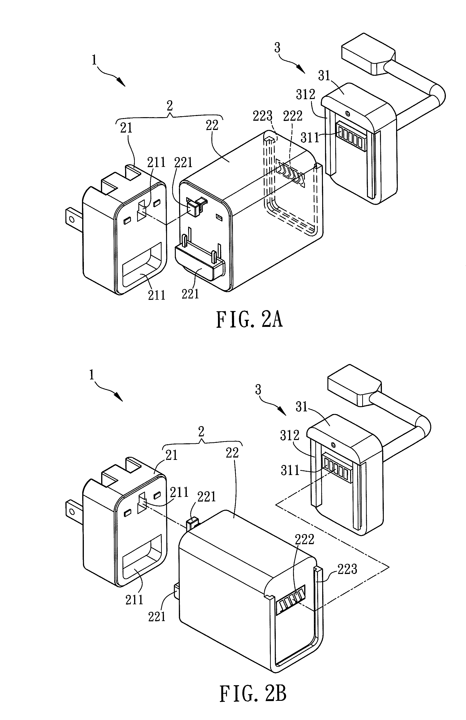
[0026]The power supply device 1 will be further illustrated with reference to FIGS. 2A and 2B. FIGS. 2A and 2B are schematic diagrams showing the separated parts of the power supply device 1 of FIG. 1. The power input module 2 has a power connecting unit 21 and a power converting unit 22. The power connecting unit 21 is detachably coupled with the power converting unit 22.

[0027]In one embodiment, the power connecting unit 21 has a receiving part 211, and the power converting unit 22 has a locking part 221. When ...


PUM


Abstract

A power supply device includes a power input module and a power functional module. The power input module has a power connecting unit and a power converting unit, which has a first connecting part. The power functional module comprises a functional unit or a plurality of functional units which connect with each other. The power input module is detachably coupled with the power functional modules of different assembling types, so that the power supply device can be transformed into various application modes. Accordingly, the power supply device can satisfy multiple applications and uses.

Description

CROSS REFERENCE TO RELATED APPLICATIONS[0001]This Non-provisional application claims priority under 35 U.S.C. §119(a) on Patent Application No(s). 100137790 filed in Taiwan, Republic of China on Oct. 18, 2011, the entire contents of which are hereby incorporated by reference.BACKGROUND OF THE INVENTION[0002]1. Field of Invention[0003]The present disclosure relates to a power supply device and, in particular, to a power supply device with a multi-functional structure.[0004]2. Related Art[0005]According to the rapid development and progress of electronic technology, many consuming electronic products, which are user-friendly, have been provided to make our lives more convenient.[0006]Therefore, a user may own many kinds of electronic products, such as cell phone, laptop, MP3 player, and the likes, at the same time. Most electronic products have corresponding specific power supply devices (adaptors). The more electronic products one user owns, the more power supply devices he / she certa...

Claims


Application Information

Patent Timeline
IPC IPC(8): H05K7/10
CPCH01R13/502H01R13/6675H01R31/065H01R29/00H01R27/00
Inventor SHEN, YU-CHENG
Owner ASUSTEK COMPUTER INC
Why Eureka
Try Eureka