Methods and apparatus for traffic management in multi-mode switching dwdm networks

a multi-mode switching and traffic management technology, applied in electrical apparatus, multiplex communication, wavelength-division multiplex systems, etc., can solve the problems of slow deployment, unfavorable ops availability in the foreseeable future, and the conversion of optical/electrical/optical (o/e/o) to electronic switching,

Active Publication Date: 2013-04-18
UNIV HOUSTON SYST
View PDF4 Cites 15 Cited by
  • Summary
  • Abstract
  • Description
  • Claims
  • Application Information

AI Technical Summary

Benefits of technology

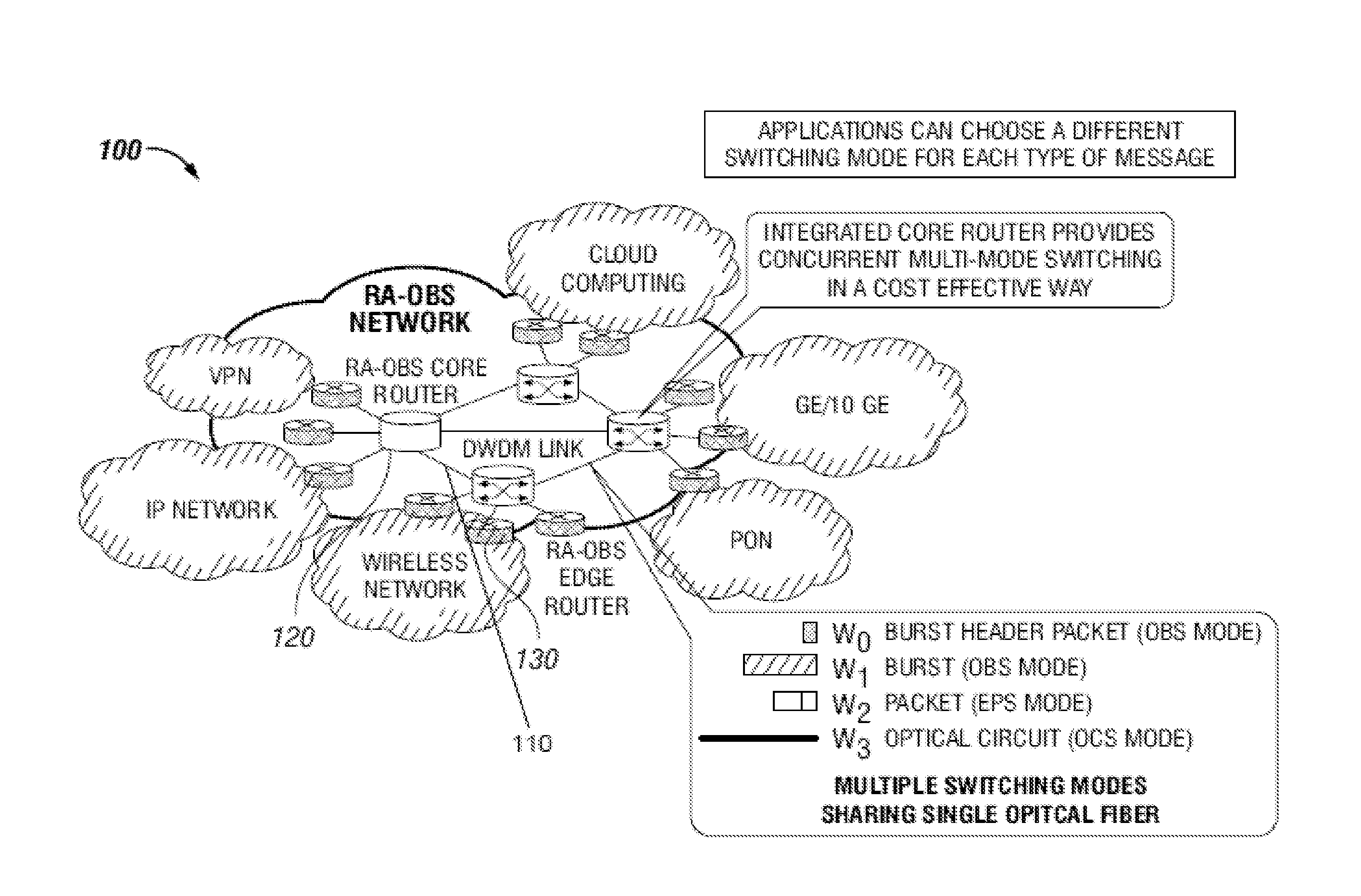
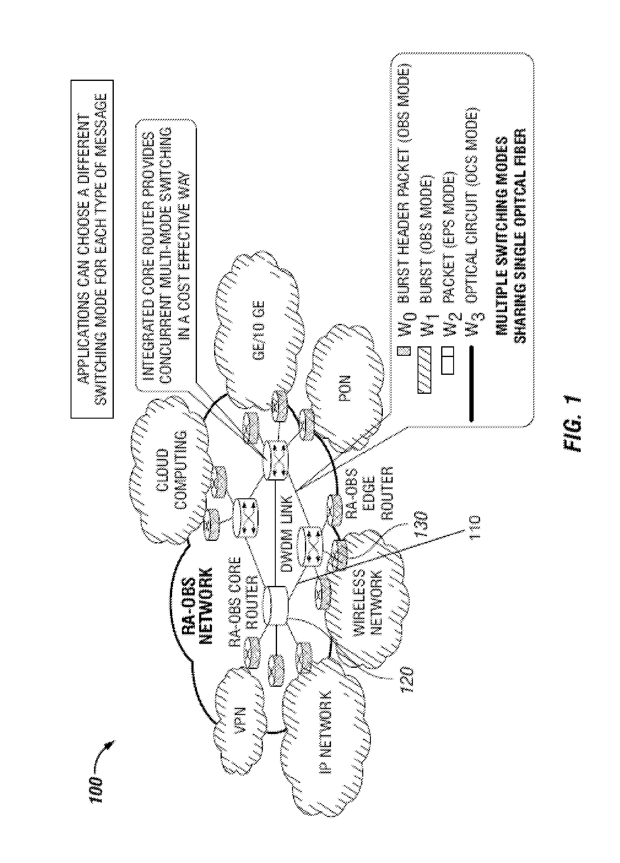
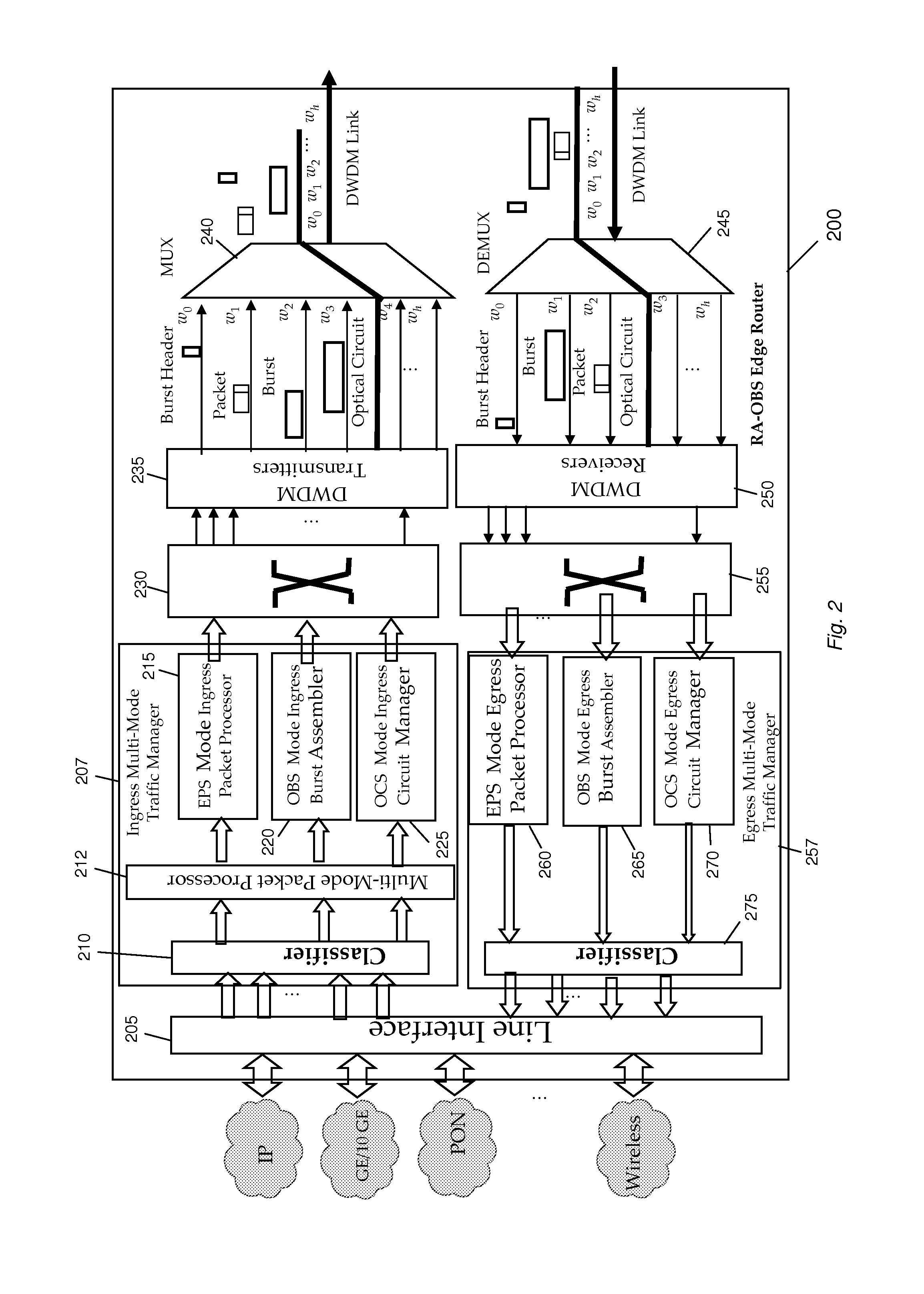
[0010]In one illustrative implementation, an edge router system for multi-mode switching comprises a traffic management module receiving data from one or more sources. The traffic management module comprises a multi-mode packet processor receiving said data that processes it for transmission in EPS, OBS, and / or OCS modes. An EPS mode processor may receive a first portion of the data from the packet processor, wherein the EPS mode processor assembles the first portion of data for transmission in an EPS mode on a first wavelength. An OBS mode processor may receive a second portion of the data from the packet processor, wherein the OBS mode processor assembles the second portion of data into burst for transmission in an OBS mode on a second wavelength. An OCS mode processor may receive a third portion of the data from the packet processor, wherein the OCS mode processor transmits the third portion of data in an OCS mode on a third wavelength. A switching control coupled to the multi-mode packet processor generates control packets for EPS, OCS, and OBS data. A multiplexer combines the control packets and the EPS, OCS, and OBS data for output to a WDM link.
[0011]In another illustrative implementation, a method for multi-mode edge routing comprising receiving data from one or more sources at an edge router for transmission via a WDM link. A first portion of the data may be routed to an electronic packet switching (EPS) mode processor that assembles the first portion of data in an EPS mode on a first wavelength. A second portion of the data may be routed to an optical burst switching (OBS) mode processor that assembles the second portion of data into burst for transmission in an OBS mode on a second wavelength. A third portion of the data may be routed to an optical circuit switching (OCS) mode processor that transmits the third portion of data in an OCS mode on a third wavelength. The EPS, OBS, and OCS data are combined for output to a WDM link.

Problems solved by technology

However, as the number of DWDM channels increases, the optical / electrical / optical (O / E / O) conversion required by electronic switching adds significantly to the overall system cost.
Although the technology has been available for the past several years, its deployment has been slow due to its coarse granularity which limits its application in supporting dynamic traffic.
It is unlikely that OPS will be available in the foreseeable future, largely due to the lack of random access optical buffers, and the synchronization issues associated with the packet header and payload.
Unfortunately, there is no single switching technology that can scale cost-effectively with the number of DWDM channels while meeting the diverse needs of heterogeneous applications.
It seems that no single switching technology (EPS, OCS or OBS) can claim victory over all applications.
Although optical switching technologies have advantages for scaling up DWDM systems, neither OCS nor OBS can switch at the packet level.
Even between the two optical switching technologies, OCS and OBS, it is hard to declare a winner for all types of applications.
However, for some applications, this implies a higher capital investment, separate management issues for each type of networks, and less flexibility; for others, unfortunately, there is no single type of network that can best fit the need for the application because of the characteristics of different types of messages within the application.
Although attempts have been made to support specific applications in the network, none of them address the DWDM channel scaling issue.

Method used


Image

  • Methods and apparatus for traffic management in multi-mode switching dwdm networks
  • Methods and apparatus for traffic management in multi-mode switching dwdm networks
  • Methods and apparatus for traffic management in multi-mode switching dwdm networks

Examples


Embodiment Construction

[0044]Refer now to the drawings wherein depicted elements are not necessarily shown to scale and wherein like or similar elements are designated by the same reference numeral through the several views.

[0045]Referring to the drawings in general, it will be understood that the illustrations are for the purpose of describing particular implementations of the disclosure and are not intended to be limiting thereto. While most of the terms used herein will be recognizable to those of ordinary skill in the art, it should be understood that when not explicitly defined, terms should be interpreted as adopting a meaning presently accepted by those of ordinary skill in the art.

[0046]It is to be understood that both the foregoing general description and the following detailed description are exemplary and explanatory only, and are not restrictive of the invention, as claimed. In this application, the use of the singular includes the plural, the word “a” or “an” means “at least one”, and the use...


PUM


Abstract

A Wavelength Division Multiplexing (WDM) multi-mode switching system and method and method provides concurrent switching in various switching modes including, but not limited to, an electronic packet switching (EPS) mode, optical circuit switching (OCS) mode, and optical burst switching (OBS) mode. Edge routers in the WDM multi-mode switching systems may provide a traffic management module that processes incoming data and routes the data for transmission in an electronic packet switching (EPS), optical burst switching (OBS), or optical circuit switching (OCS) modes via a WDM link.

Description

RELATED APPLICATIONS[0001]This application claims the benefit of U.S. Provisional Patent Application No. 61 / 469,337, filed on Mar. 30, 2011, which is incorporated herein by reference.STATEMENT REGARDING FEDERALLY SPONSORED RESEARCH[0002]This invention was made with government support under Grant Nos. CNS-0708613, CNS-0923481 and ECCS-0926006 awarded by the National Science Foundation. The government has certain rights in the invention.FIELD OF THE INVENTION[0003]The present invention relates to a method for enhancing traffic management in optical networks. More specifically, the present invention enables efficient dynamic packet traffic management in Dense Wavelength Division Multiplexing (DWDM) networks.BACKGROUND OF INVENTION[0004]With the advent of 10 Gigabit Ethernet and Fiber-to-the-Home (FTTH) with the Passive Optical Network (PON), residential user data rate is expected to exceed 100 Mb / s in the near future, and over 1 Gb / s in the long term, while enterprise users will enjoy ...

Claims


Application Information

Patent Timeline
Patent Type & Authority Applications(United States)
IPC IPC(8): H04J14/02
CPCH04L45/62H04J14/02H04J14/0212H04J14/0284H04J14/0267H04J14/0268H04J14/0283H04J14/0257
Inventor CHEN, YUHUA
Owner UNIV HOUSTON SYST
Why Eureka
Try Eureka