Image forming apparatus

Active Publication Date: 2013-04-18
KONICA MINOLTA BUSINESS TECH INC
View PDF0 Cites 2 Cited by
  • Summary
  • Abstract
  • Description
  • Claims
  • Application Information

AI Technical Summary

Benefits of technology

The purpose of this invention is to make it easier to remove sheets that get jammed in an image forming apparatus without damaging the apparatus.

Problems solved by technology

However, for example, in a case where a large number of sheets of paper are carried in an image forming apparatus during processing, such as a case where an image forming apparatus having a PFU performs double-sided printing, it is necessary to remove not only a jammed sheet but also sheets being carried (remaining sheets) in the image forming apparatus when a jam occurs.
Accordingly, there is a plurality of locations from which the sheets need to be removed, so that it takes time and trouble to recover the image forming apparatus.
However, because the technology proposed by the Japanese Patent Application Laid-Open Publication No. 2002-268299 is a technology to accumulate remaining sheets on a reverse paper path, it is difficult to remove the accumulated remaining sheets.
In addition, the technology proposed by the Japanese Patent Application Laid-Open Publication No. 2002-268299 does not take the sizes of the remaining sheets into account, and hence, regardless of the sizes of the remaining sheets, the accumulation is performed in the same manner.
Consequently, there is a possibility that a secondary jam is caused by the accumulation, or the apparatus is damaged thereby and the like.

Method used


Image

  • Image forming apparatus
  • Image forming apparatus
  • Image forming apparatus

Examples


Embodiment Construction

[0021]In the following, an image forming apparatus in accordance with an embodiment of the present invention is described in detail, referring to the accompanying drawings. However, the present invention is not limited to the embodiment the drawings.

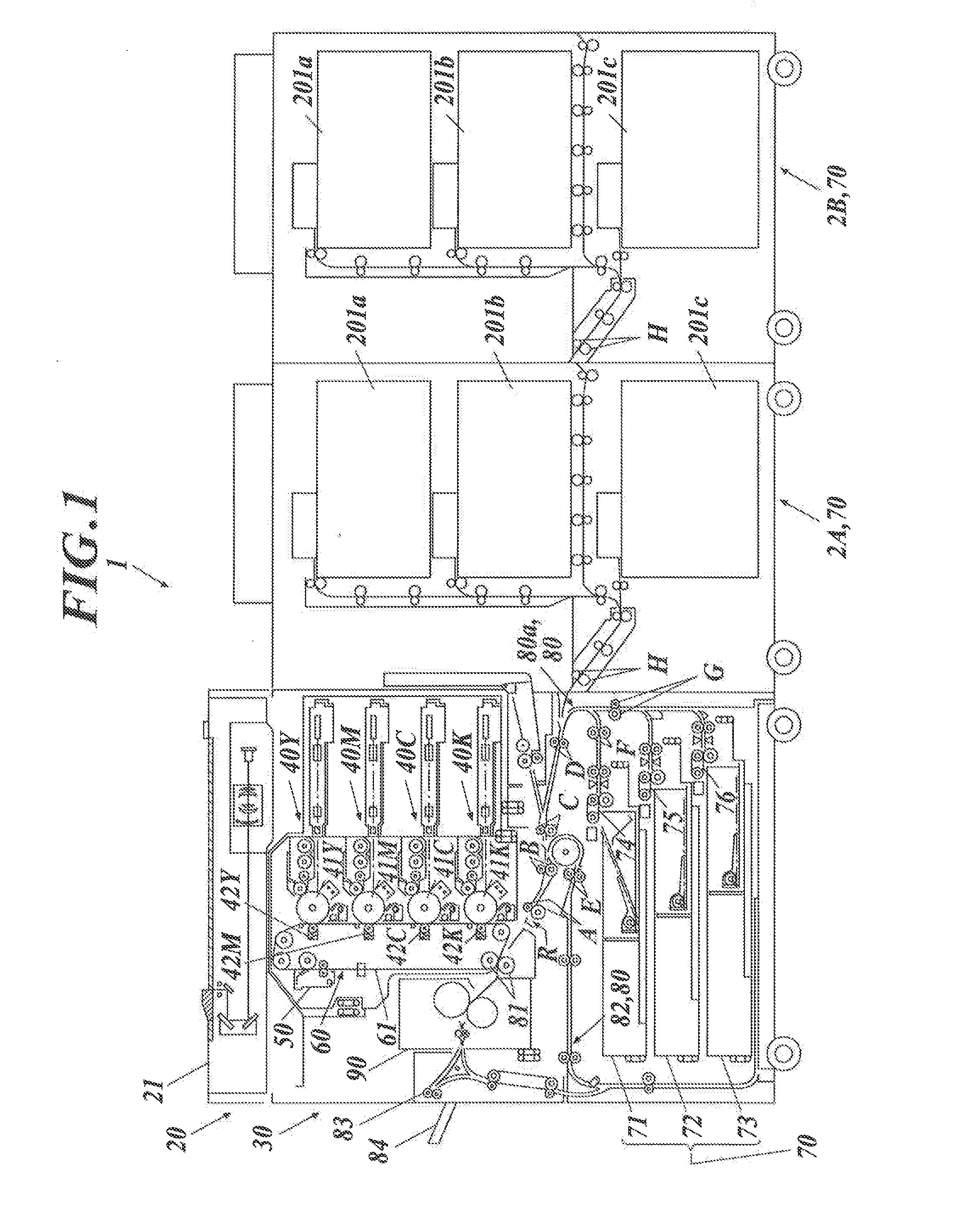
[0022]FIG. 1 is a cross-sectional view schematically showing a configuration of an image forming apparatus 1 in accordance with an embodiment of the present invention.

[0023]The image forming apparatus 1 is a digital multifunction printer (MFP) having a copier function, a printer function, and the like. The copier function is a function to read images from reading target documents NP (“document” hereinafter) and form the read images on paper such as flat paper as processing target paper. The printer function is a function to receive image data from a personal computer or the like, form images on paper on the basis of the received image data, and output the images. The image forming apparatus 1 has an openable / closable front door (not show...


PUM


Abstract

An image forming apparatus includes a carrying unit, a resistance unit, a jam detection unit, a paper detection unit and a control unit. Responding to the jam detection unit detecting that a jam occurring location is outside the resistance unit, the control unit sets a part of the carrying unit, the part including at least the resistance unit, as an accumulation unit where a remaining sheet is accumulated, in accordance with a size of the remaining sheet. The remaining sheet is detected by a paper detection unit when the jam occurs. The control unit releases, among a resistance roller pair and carrying roller pairs of the carrying unit, the rollers of a pair located in the accumulation unit from pressing against each other, and makes the carrying unit carry the remaining sheet to the accumulation unit.

Description

BACKGROUND OF THE INVENTION[0001]1. Field of the Invention[0002]The present invention relates to an image forming apparatus.[0003]2. Description of the Related Art[0004]Conventionally, there is known an image forming apparatus, such as a copier, including a paper feeding tray unit, which is referred to as PFU (paper Feeder Unit), having a plurality of paper feeding trays, so that a large number of sheets of paper are able to be fed thereinto. There is also known an image forming apparatus having a mechanism to perform printing processing on both sides of paper (double-sided printing) in addition to printing processing on one side of paper (single-sided printing).[0005]If a paper jam occurs in these image forming apparatuses, the image forming apparatuses immediately stop carrying sheets of paper. In order to restart the image forming apparatuses, it is necessary to remove the jammed sheet jammed therein.[0006]However, for example, in a case where a large number of sheets of paper ar...

Claims


Application Information

Patent Timeline
IPC IPC(8): G03G15/00
CPCG03G21/1638G03G15/70
Inventor ARAI, HIROYUKI
Owner KONICA MINOLTA BUSINESS TECH INC
Why Eureka
Try Eureka