Eureka AIR delivers breakthrough ideas for toughest innovation challenges, trusted by R&D personnel around the world.

Dental Appliance and Method for Removing Bodily and Other Fluids From a Dental Site

a dental appliance and bodily fluid technology, applied in the field of dental appliances, can solve the problems of affecting the visibility and access of dental sites, cotton rolls become overly wet with saliva, and the soft tissues are traumatized, so as to improve visibility and access.

Inactive Publication Date: 2013-04-18
AMES INGER MARIE
View PDF30 Cites 33 Cited by
  • Summary
  • Abstract
  • Description
  • Claims
  • Application Information

AI Technical Summary

Benefits of technology

This patent aims to improve dental procedures by retracting the patient's cheeks and lips to provide better visibility and access for the dental practitioner. It also allows the patient to close their jaw while still being able to breathe. The invention features a dental device that is placed in the mouth and is easy to use, comfortable for the patient, and safe disposable after only one use.

Problems solved by technology

During use, tissues become trapped in the opening, thereby obstructing suction and causing trauma to the soft tissues.
Further, the saliva ejectors evacuate only one side of the mouth at a time, and impede visibility and access to dental sites.
Although cotton rolls may be placed in the oral vestibule for retraction, the cotton rolls become overly wet with saliva during the dental procedure.
These devices retract only one area at a time, and must be held in place by a dental practitioner which can result in operator fatigue.
Other retraction devices are bulky, cumbersome, obstruct visibility, and can be used on only one side of the mouth at a time.
These devices are bulky, restrict visibility, and allow access to only one side of the mouth at a time.
In addition, the dimensions of the device prohibit placement in certain patients that are unable to sufficiently open their mouth.

Method used


Image

  • Dental Appliance and Method for Removing Bodily and Other Fluids From a Dental Site
  • Dental Appliance and Method for Removing Bodily and Other Fluids From a Dental Site
  • Dental Appliance and Method for Removing Bodily and Other Fluids From a Dental Site

Examples


Embodiment Construction

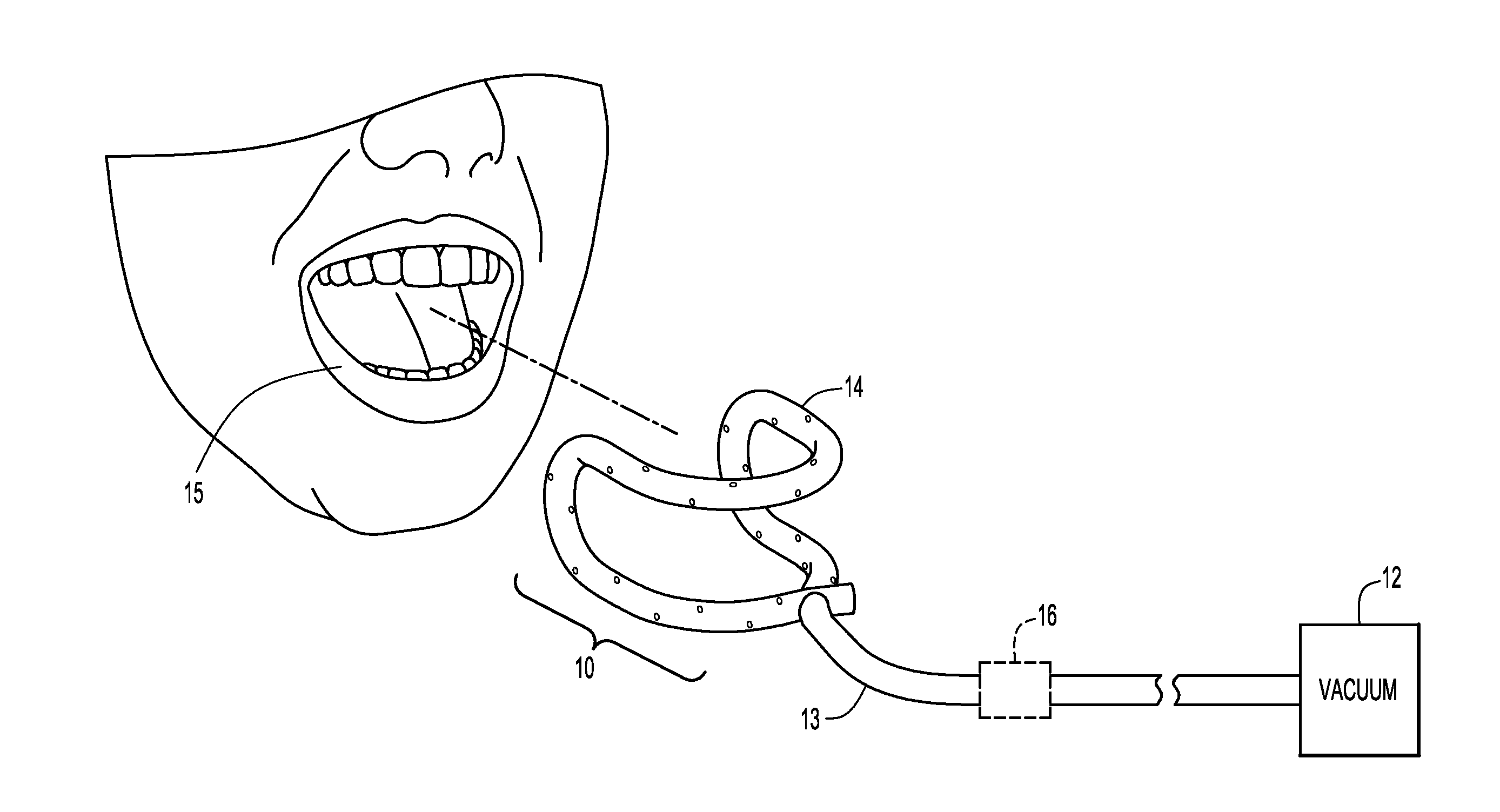
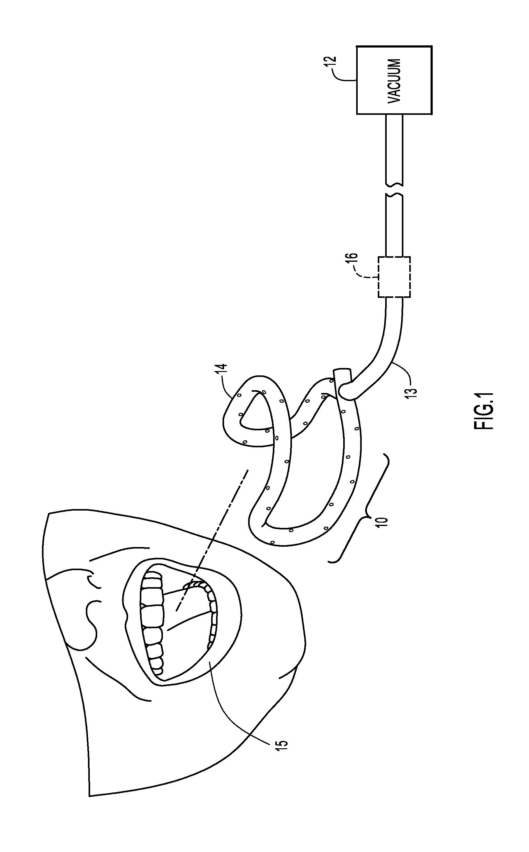
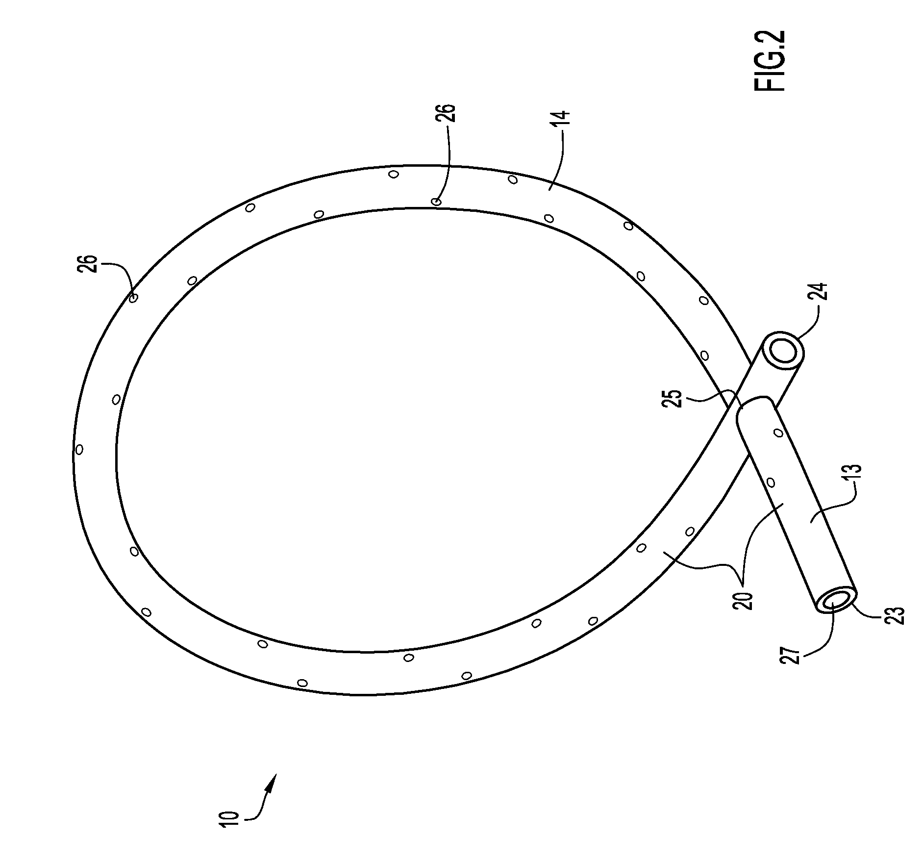
[0021]A dental appliance to remove bodily and / or other fluids (e.g., saliva, water, etc.), retract lips and / or cheeks, and maintain a patient mouth in an open state during dental procedures is illustrated in FIG. 1. Specifically, a dental appliance 10 includes a flexible looped section 14 that is manipulated to fit within a patient oral vestibule 15 (e.g., a region between the lips or cheeks and the teeth, maxilla, or mandible). The dental appliance further comprises a connector section 13 that is coupled to a vacuum or suction system 12 at interface 16. The vacuum system may be implemented by any suitable dental or other vacuum system, and applies suction to the dental appliance to remove bodily and / or other fluids from the patient mouth during dental procedures. Looped section 14 includes perforations to enable the bodily and / or other fluids to be drawn into the looped section via the suction provided by vacuum device 12. In addition, looped section 14 is resilient and further ser...


PUM


Abstract

According to a present invention embodiment, a dental appliance maintains a patient mouth in an open state, retracts tissue, and evacuates bodily and / or other fluids from a dental site. The dental appliance includes an elongated tube configured with a looped section. The elongated tube is flexible, where the looped section is adjustable and manipulated to enable the dental appliance to accommodate mouths of various dental patients. Further, the looped section is resilient in order to maintain the patient mouth in an open state for dental procedures. In addition, the elongated tube includes perforations to remove bodily or other fluids from the patient mouth. A vacuum or suction device is coupled to an end of the elongated tube, where suction is applied to the tube to draw bodily or other fluids from the patient mouth through the perforations and remove these fluids from a dental site.

Description

CROSS-REFERENCE TO RELATED APPLICATION[0001]This application claims priority from U.S. Provisional Patent Application Ser. No. 61 / 547,084, entitled “Saliva Ejector” and filed Oct. 14, 2011, the disclosure of which is incorporated herein by reference in its entirety.BACKGROUND[0002]1. Technical Field[0003]Present invention embodiments relate to dental appliances and, in particular, to devices for propping the mouth open, retracting tissue, and evacuating fluids from the mouth.[0004]2. Discussion of Related Art[0005]Dental practitioners and technicians remove saliva and water from a mouth, retract lips and cheeks, and prop the mouth open during dental procedures in order to provide a dry and unobstructed field of operation. Typically, separate devices are utilized to perform these functions.[0006]In particular, saliva ejectors are employed to evacuate saliva from a dental site. Generally, the saliva ejectors comprise a plastic tube with a wire to provide stability, and have a single o...

Claims


Application Information

Patent Timeline
Patent Type & Authority Applications(United States)
IPC IPC(8): A61C17/10A61C17/08
CPCA61C17/043A61C17/08
Inventor AMES, INGER-MARIE
Owner AMES INGER MARIE
Why Eureka
Eureka Blog
Learn More