Crimp terminal, connection structural body and connector

a technology of connection structure and crimp terminal, which is applied in the direction of vehicle connectors, connections effected by permanent deformation, and connection contact material, etc. it can solve the problems of reducing conductivity, corroding insulated wires, and increasing the complexity of electric circuits of such circuits, and achieve the effect of ensuring the property of moisture stoppag

Active Publication Date: 2013-04-18
FURUKAWA ELECTRIC CO LTD +1
View PDF10 Cites 66 Cited by
  • Summary
  • Abstract
  • Description
  • Claims
  • Application Information

AI Technical Summary

Benefits of technology

[0048]According to the present invention, a crimp terminal, a connection structural body, and a connector which can have the moisture stop property with certainty merely by pressure-bonding performed by the pressure-bonding section are provided.

Problems solved by technology

Today, automobiles are equipped with various electric and electronic parts, electric circuits thereof are becoming more and more complicated.
The electric circuit constructed by such electric connection has a problem that when moisture invades a pressure-bonded section at which the insulated wire is pressure-bonded to the crimp terminal located in the connector, a surface of the electric wire conductor included in the insulated wire is corroded and thus the conductivity thereof is decreased.
However, recent electric circuits having a complicated structure need to have a more stable conductivity.
Thus, the above-described crimp terminal is not sufficient.
As a result, a sufficient conducting function may not be provided.
However, application of a paint at the time of pressure-bonding is not preferable for mass production because additional time is needed for the step of application.
It is also very difficult to apply a paint while the position and the amount of application are controlled with high precision at the time of pressure-bonding.
For these reasons, the method of applying an epoxy paint at the time of pressure-bonding is not satisfactory.

Method used


Image

  • Crimp terminal, connection structural body and connector
  • Crimp terminal, connection structural body and connector
  • Crimp terminal, connection structural body and connector

Examples


Embodiment Construction

[0058]An embodiment of the present invention will be described with reference to the drawings.

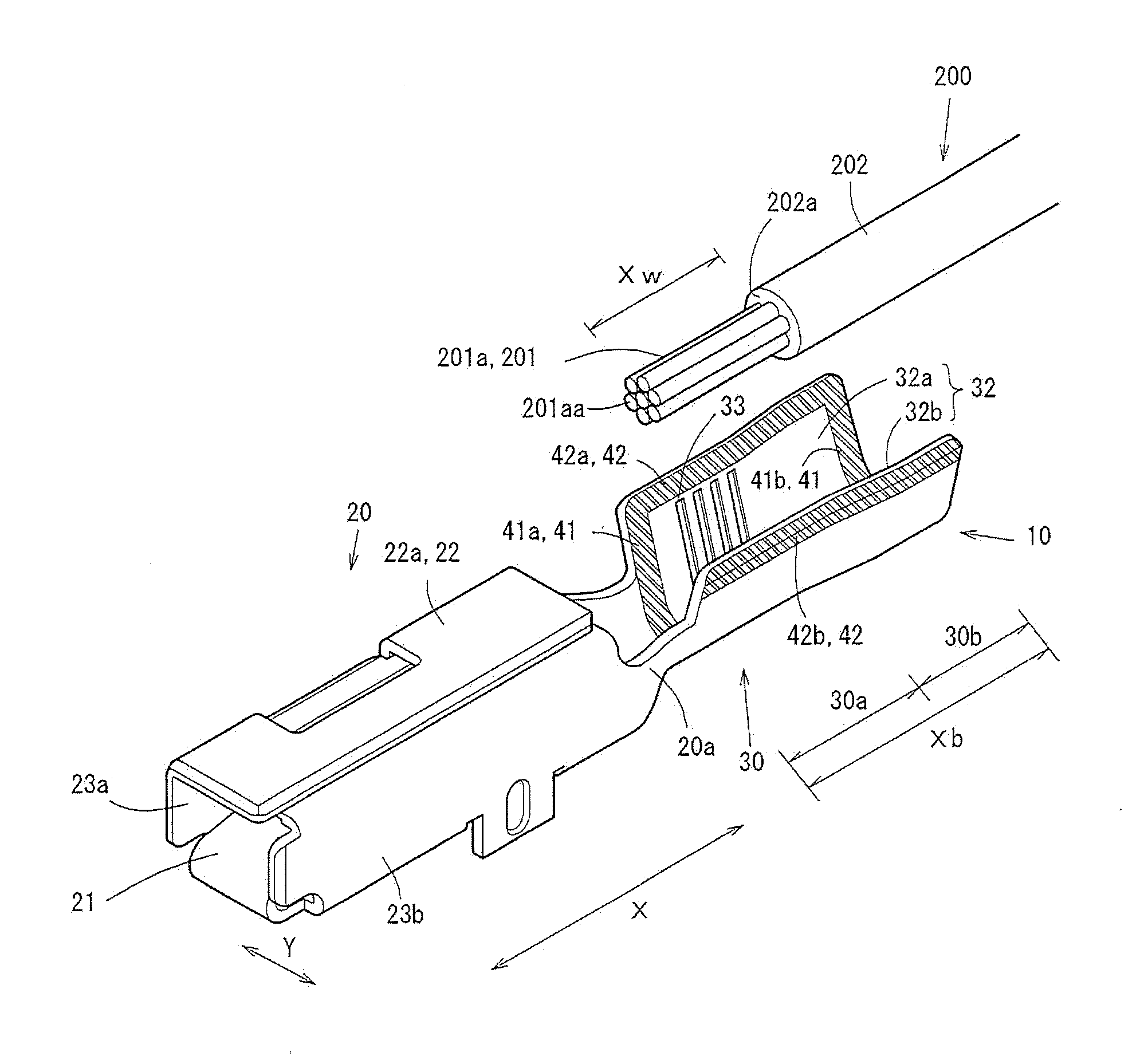
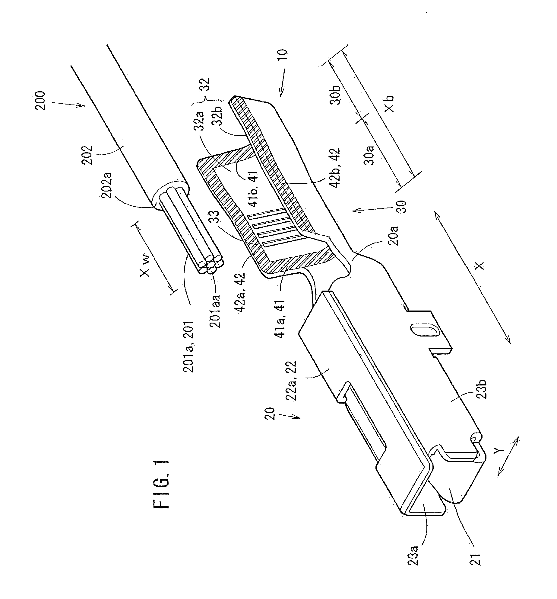
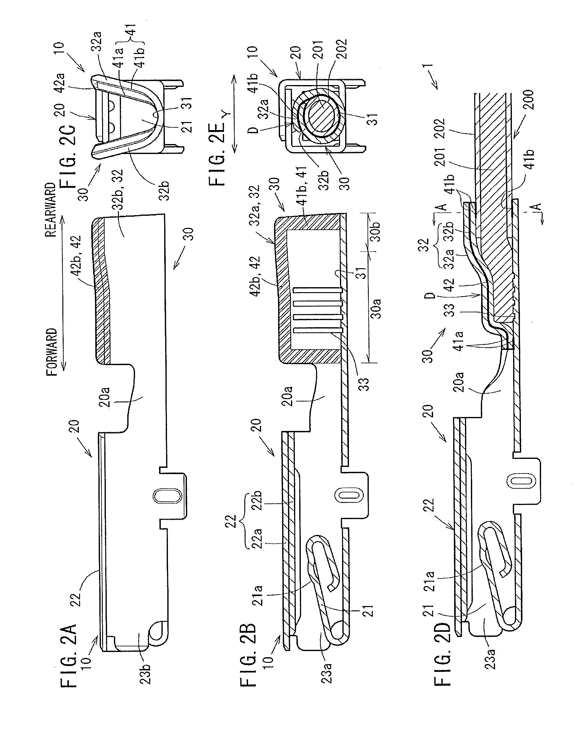
[0059]FIG. 1 is an isometric view of a female crimp terminal 10, and FIG. 2 illustrates the female crimp terminal 10. FIG. 2(A) is a side view of the female crimp terminal 10. FIG. 2(B) is a longitudinal cross-sectional view of the female crimp terminal 10 taken along a central line in a width direction thereof. FIG. 2(C) is a rear view of the female crimp terminal 10. FIG. 2(D) is a longitudinal cross-sectional view of a pressure-bonding connection structural body 1 taken along a central line in the width direction thereof. FIG. 2(E) is a lateral cross-sectional view of the pressure-bonding connection structural body 1 taken along line A-A, which is in a rear part of a pressure-bonding section 30 of the pressure-bonding connection structural body 1 shown in FIG. 2(D).

[0060]FIG. 3 illustrates a chain terminal 110 used to form the female crimp terminal 10. More specifically, FIG. 3(A) is a p...


PUM


Abstract

A crimp terminal includes barrel pieces respectively on both of two sides in a width direction thereof. The barrel pieces are included in a pressure-bonding section for pressure-bonding an exposed part of an electric wire conductor of an insulated wire. The insulated wire includes the electric wire conductor and an insulating cover for covering an outer circumference of the electric wire conductor, and the exposed part is a part of the electric wire conductor which is exposed from a tip of the cover by a predetermined length. The barrel pieces have a length in a longitudinal direction which is longer than the length of the exposed part of the electric wire conductor. The pressure-bonding section pressure-bonds, by the barrel pieces, a continuous part from a tip of the electric wire conductor to a position rear to the tip of the cover.

Description

TECHNICAL FIELD[0001]The present invention relates to a crimp terminal attachable to, for example, a connector or the like for connection of a wire harness for an automobile, a connection structural body including the same, and a connector having such a connection structural body located therein.BACKGROUND ART[0002]Today, automobiles are equipped with various electric and electronic parts, electric circuits thereof are becoming more and more complicated. Thus, stable supply of power is indispensable. An automobile equipped with such various electric and electronic parts includes wire harnesses including insulated wires in a bundle. The wire harnesses are connected to each other by connectors to form an electric circuit.[0003]Such a connector has a built-in crimp terminal for pressure-bonding and thus connecting an insulated wire thereto by a pressure-bonding section. A male connector and a female connector are in engagement with each other.[0004]The electric circuit constructed by s...

Claims


Application Information

Patent Timeline
Patent Type & Authority Applications(United States)
IPC IPC(8): H01R4/18
CPCH01R4/184H01R4/70H01R13/52H01R2201/26H01R4/18H01R4/188H01R4/62H01R43/005
Inventor MITOSE, KENGOKIHARA, YASUSHIKAWAMURA, YUKIHIRO
Owner FURUKAWA ELECTRIC CO LTD
Why Eureka
Try Eureka