Charger Alignment in an Implantable Medical Device System Employing Reflected Impedance Modulation

a technology of impedance modulation and charger, which is applied in the field of wireless external chargers for use in implantable medical device systems, can solve the problems of poor coupling, external charger b>50/b> to heat up, and possibly burn or injure the patient, and non-idealities cannot be avoided

Active Publication Date: 2013-04-18
BOSTON SCI NEUROMODULATION CORP
View PDF4 Cites 99 Cited by
  • Summary
  • Abstract
  • Description
  • Claims
  • Application Information

AI Technical Summary

Problems solved by technology

Poor coupling is disfavored, as this will require high power drain (i.e., a high Icharge) in the external charger 50 to adequately charge the IPG battery 26.
The use of high power depletes the batteries 76 (if any) in the external charger 50, and more importantly can cause the external charger 50 to heat up, and possibly burn or injure the patient.
Some of these non-idealities cannot be avoided after implantation: for example, if the IPG 100 is deeply implanted (FIG. 4D), or implanted at an angle (FIG. 4C), poor coupling with the external charger 50 may be unavoidable.
However, many prior alignment approaches are complicated, requiring significant and expensive modifications to the external charger 50.
However, because the magnetic charging field is relatively intense compared to fields typically used to telemeter data and thus could interfere with such telemetry, the external charger 50 must periodically suspend the magnetic charging field to allow the telemetry coupling data to be received from the IPG 100.
This adds cost and complexity to the external charger 50.

Method used


Image

  • Charger Alignment in an Implantable Medical Device System Employing Reflected Impedance Modulation
  • Charger Alignment in an Implantable Medical Device System Employing Reflected Impedance Modulation
  • Charger Alignment in an Implantable Medical Device System Employing Reflected Impedance Modulation

Examples


Embodiment Construction

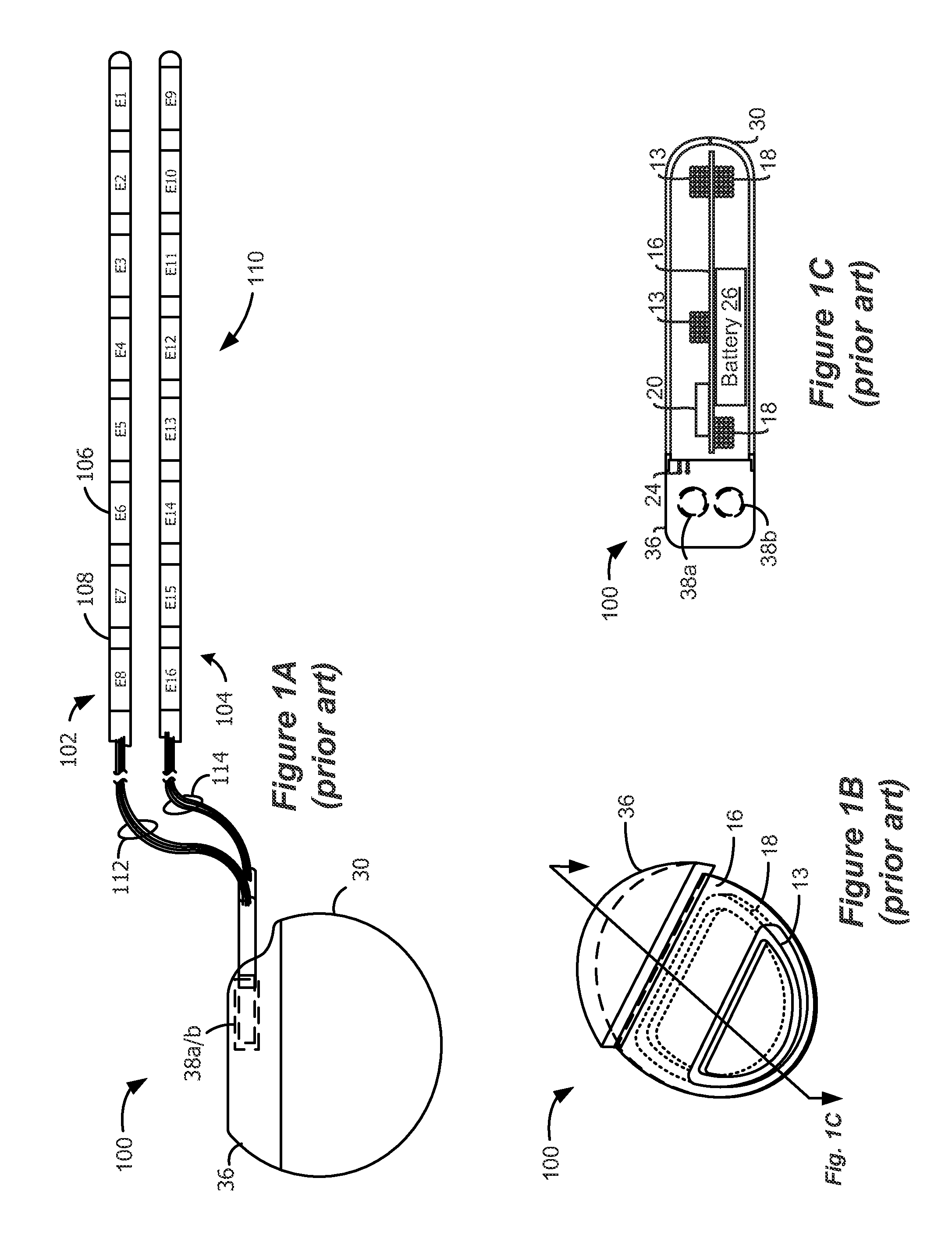
[0030]The description that follows relates to use of the invention within a spinal cord stimulation (SCS) system. However, it is to be understood that the invention is not so limited, and could be used with any type of implantable medical device system.

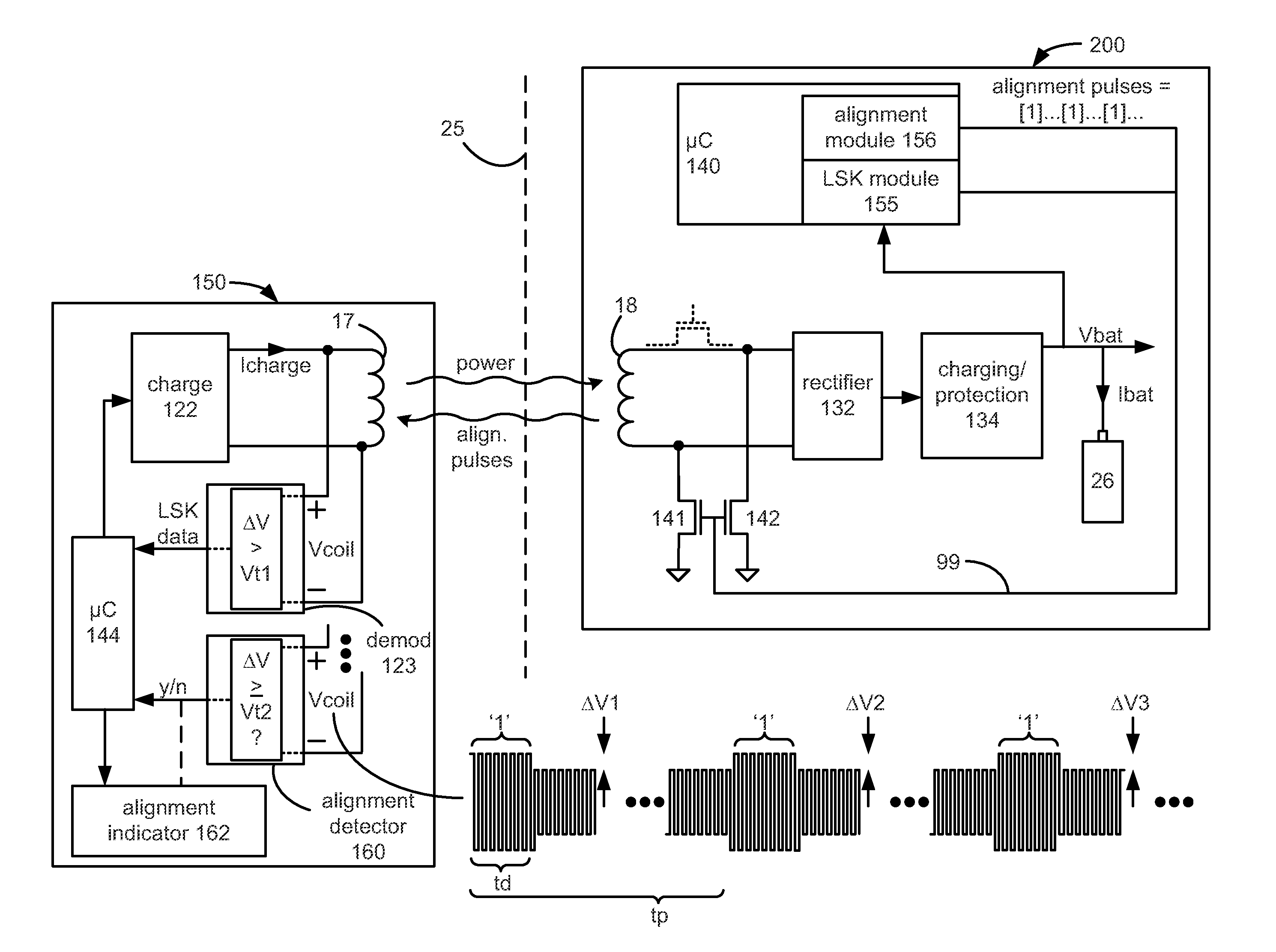
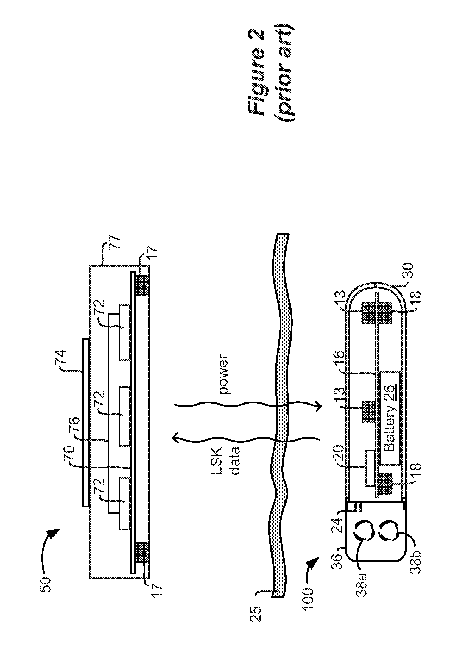
[0031]The disclosed means of determining alignment between an external charger and an implantable medical device such as an IPG involves the use of reflected impedance modulation, i.e., by measuring at the external charger reflections arising from modulating the impedance of the charging coil in the IPG. Reflected impedance modulation has been used in legacy systems to enable Load Shift keying (LSK) telemetry to send data to the external charger to control charging, as discussed in the Background. However, the alignment detection method of this disclosure doesn't involve data transmission, although some of the same LSK hardware can be used. During charging, the charging coil in the IPG is periodically pulsed to modulate its impedance....


PUM


Abstract

The disclosed means of determining alignment between an external charger and an implantable medical device (IMD) involves the use of reflected impedance modulation, i.e., by measuring at the external charger reflections arising from modulating the impedance of the charging coil in the IMD. During charging, the charging coil in the IMD is pulsed to modulate its impedance. The difference in the coil voltage (ΔV) produced at the external charger as a result of these pulses is assessed and is used by the external charger to indicate coupling. If the magnitude of ΔV is above a threshold, the external charger considers the coupling to the IMD to be adequate, and an alignment indicator in the external charger is controlled accordingly. The magnitude of Vcoil can be assessed in addition to ΔV to determine alignment with the IMD with improved precision, and/or to further define a high quality alignment condition.

Description

CROSS REFERENCE TO RELATED APPLICATIONS[0001]This is a non-provisional filing of U.S. Provisional Patent Application Ser. No. 61 / 546,850, filed Oct. 13, 2011, which is incorporated herein and to which priority is claimed.[0002]This application is related to a U.S. Provisional Patent Application Ser. No. 61 / 546,871, filed Oct. 13, 2011.FIELD OF THE INVENTION[0003]The present invention relates to wireless external chargers for use in implantable medical device systems.BACKGROUND[0004]Implantable stimulation devices are devices that generate and deliver electrical stimuli to body nerves and tissues for the therapy of various biological disorders, such as pacemakers to treat cardiac arrhythmia, defibrillators to treat cardiac fibrillation, cochlear stimulators to treat deafness, retinal stimulators to treat blindness, muscle stimulators to produce coordinated limb movement, spinal cord stimulators to treat chronic pain, cortical and deep brain stimulators to treat motor and psychologica...

Claims


Application Information

Patent Timeline
Patent Type & Authority Applications(United States)
IPC IPC(8): A61N1/378
CPCA61N1/37252A61N1/3787A61F2250/0001
Inventor OZAWA, ROBERTAGHASSIAN, DANIEL
Owner BOSTON SCI NEUROMODULATION CORP
Why Eureka
Try Eureka