Cutting Device, Method and Use for Cutting of a Line Extending from a Floating Vessel

Active Publication Date: 2013-04-25
SMART INSTALLATIONS
View PDF13 Cites 12 Cited by
  • Summary
  • Abstract
  • Description
  • Claims
  • Application Information

AI Technical Summary

Benefits of technology

[0091]Moreover, the cutting device and/or the fixing device may be activated and oper

Problems solved by technology

The applicant does not know of any dedicated, technical solution for cutting of a line extending from a floating vessel in context of un

Method used


Image

  • Cutting Device, Method and Use for Cutting of a Line Extending from a Floating Vessel
  • Cutting Device, Method and Use for Cutting of a Line Extending from a Floating Vessel
  • Cutting Device, Method and Use for Cutting of a Line Extending from a Floating Vessel

Examples


Embodiment Construction

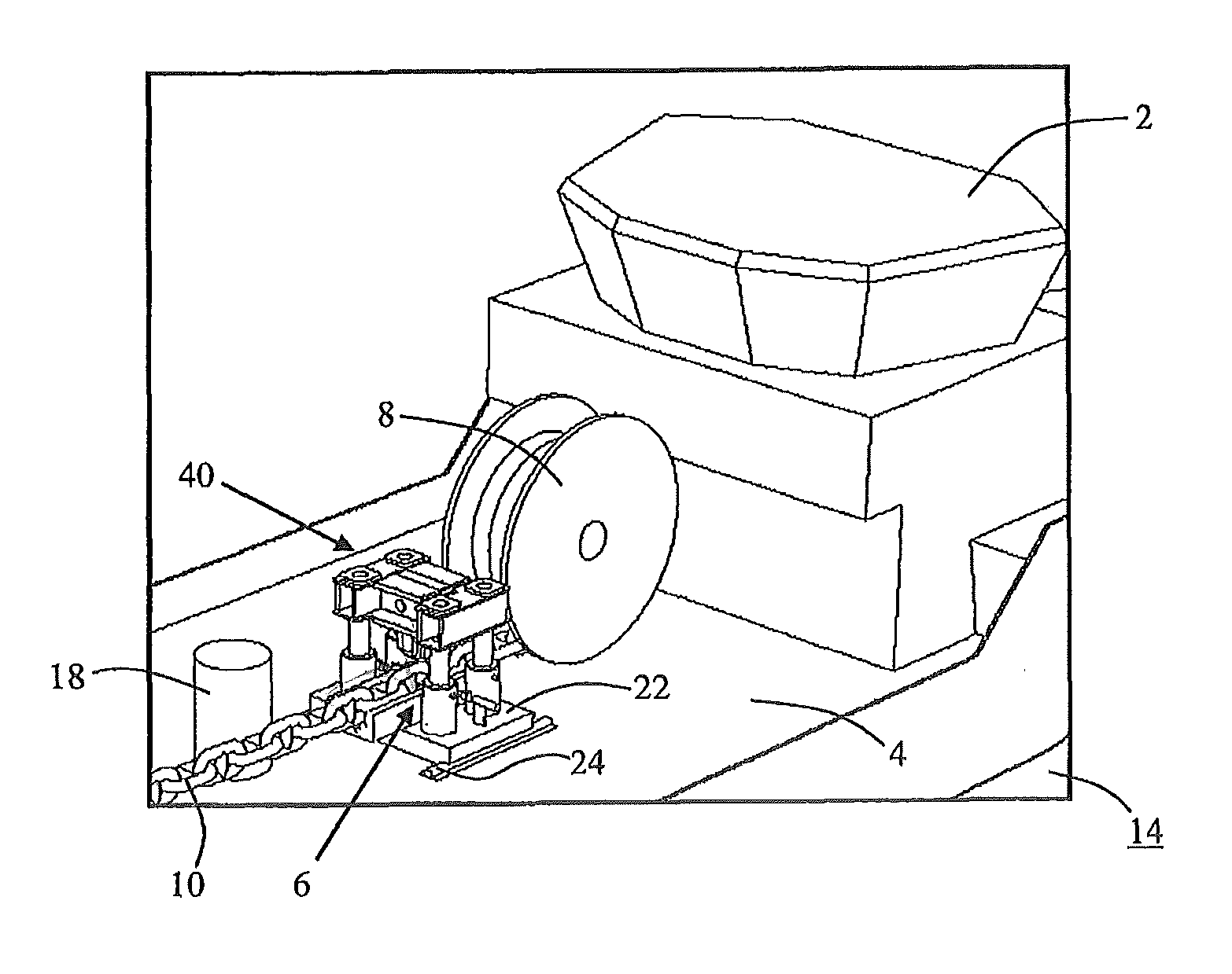
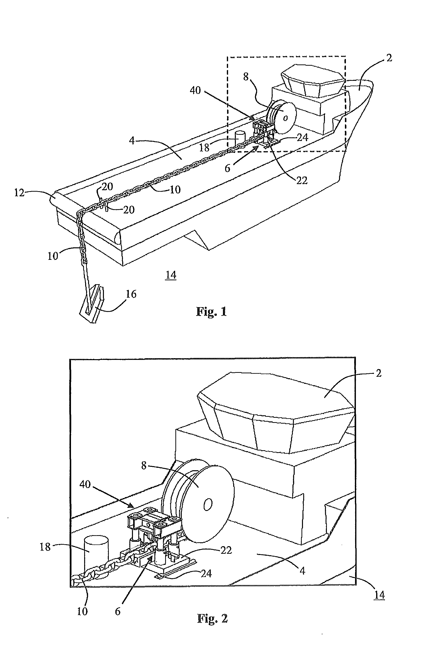
[0107]FIGS. 1 and 2 show an anchor handling vessel 2 with a deck 4 which, at the forward end thereof, is provided with, among other things, a cutting device 6 according to the invention and a large guide wheel 8 arranged between the cutting device 6 and a cabelar wheel (not shown) at the forward end of the deck 4. Via the guide wheel 8, a very heavy duty chain 10 may be spooled out or in via the cabelar wheel. The chain 10 is spooled out from / into a cargo hold (not shown) within the vessel 2. The function of the guide wheel is to guide the chain 10 correctly into the cutting device 6. The chain 10 extends from the forward to the aft end of the deck 4 and onwards over the stern 12 and down into the sea 14 where the chain 10 is connected to a large and heavy anchor 16.

[0108]For directional steering of the chain across the deck 4, the deck 4 is also provided with a support pillar 18 at the forward end thereof, and also two guide pegs 20 at the aft end thereof between which the chain 10...


PUM

PropertyMeasurementUnit
Timeaaaaaaaaaa
Areaaaaaaaaaaa

Abstract

Cutting device, method and use are for cutting of a line extending from a floating vessel. The cutting device is structured for placement on the vessel. The cutting device comprises: at least one guide structured for directional steering of the line past a cutting area for the line; and at least one of the following cutting-promoting devices: at least one induction coil device directed inwards toward the cutting area and structured for heating, hence weakening, of the line within the cutting area; and at least one moveable cutting knife with an opposite contact surface directed inwards toward the cutting area and also structured for cutting of the line within the cutting area.

Description

AREA OF INVENTION[0001]The present invention concerns a cutting device, a method and a use for cutting of a line extending from a floating vessel.[0002]For example, the vessel may be comprised of a boat or a floating installation. As an example, the boat may be comprised of an anchor handling vessel, whereas the floating installation may be comprised of a drilling rig or a drilling ship. Said line may be comprised of, for example, a chain, a wire or a fibre line, possibly an assembly of such line types.[0003]It is to be possible, by means of the present invention, to carry out a quick, controlled and safe cutting of the line on board the vessel, for example in an emergency situation. In order to avoid damage to personnel and equipment, remote-controlled cutting may also be carried out.BACKGROUND OF THE INVENTION[0004]The background of the invention is emergency situations that have occurred at sea in context of handling big loads from floating vessels, particularly during bad weathe...

Claims


Application Information

Patent Timeline
IPC IPC(8): B63B43/02B26D7/14
CPCB23D15/00B26D1/04B26D5/12B26F3/04B26D7/10B63B21/22B26D7/14B63B43/02B26D1/09B63B21/18Y10T83/04Y10T83/0424Y10T83/283Y10T83/323Y10T83/748Y10T83/7487Y10T83/7547Y10T83/8828B26F1/38B26F3/08
Inventor BIRKELAND, PETTER
Owner SMART INSTALLATIONS
Why Eureka
Try Eureka