Embossing unit and embossing method

Inactive Publication Date: 2013-04-25
FABIO PERINI SPA
View PDF7 Cites 3 Cited by
  • Summary
  • Abstract
  • Description
  • Claims
  • Application Information

AI Technical Summary

Benefits of technology

[0010]According to one aspect, the object of the invention is to entirely or partly solve one or more of the aforementioned problems. The object of a particularly advantageous embodiment o

Problems solved by technology

This process produces permanent deformations on the web material, with the possible partial breakage of some of the cellulose fibers that form the paper ply.
These operations are time-consumi

Method used


Image

  • Embossing unit and embossing method
  • Embossing unit and embossing method

Examples


Example

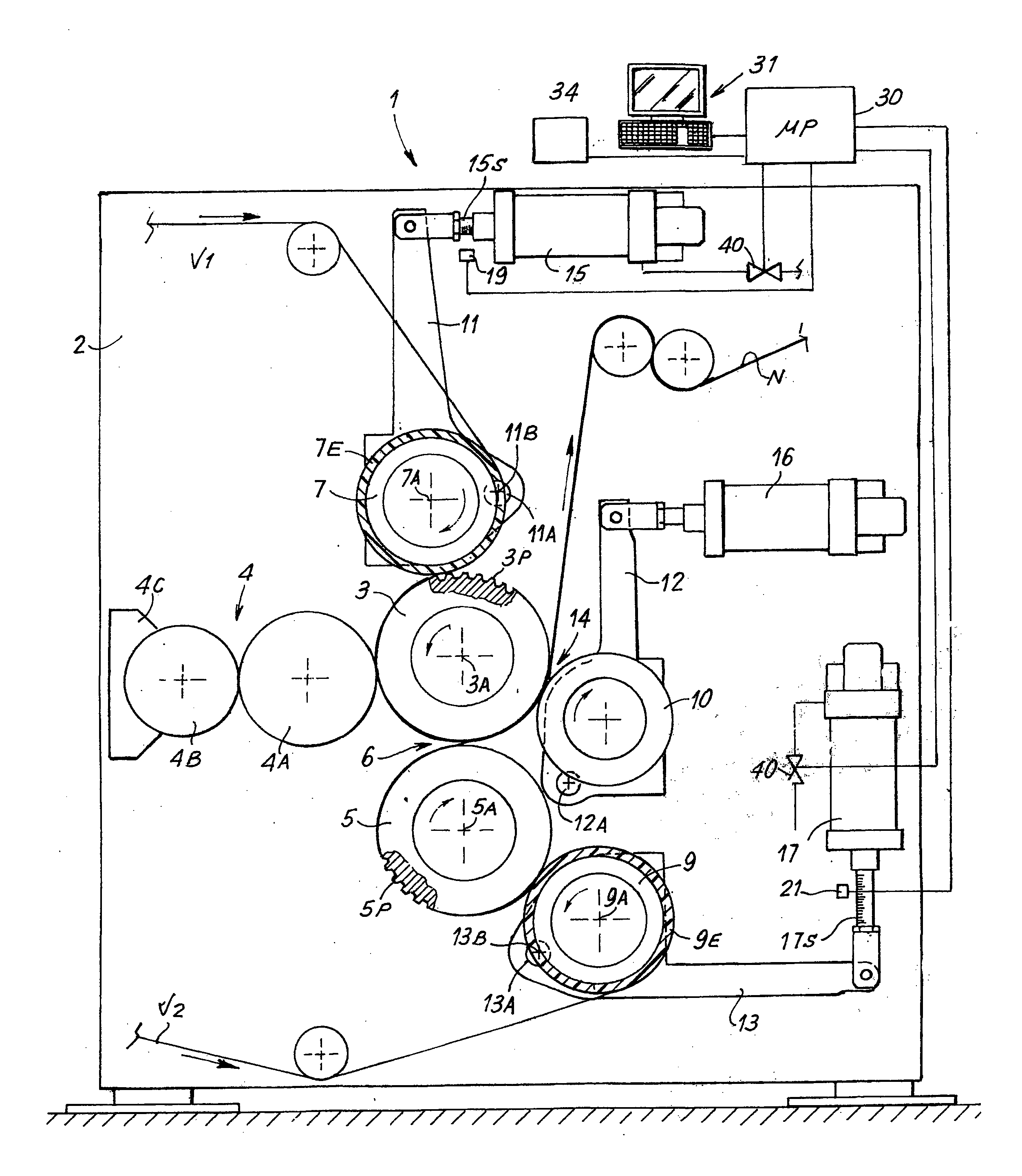
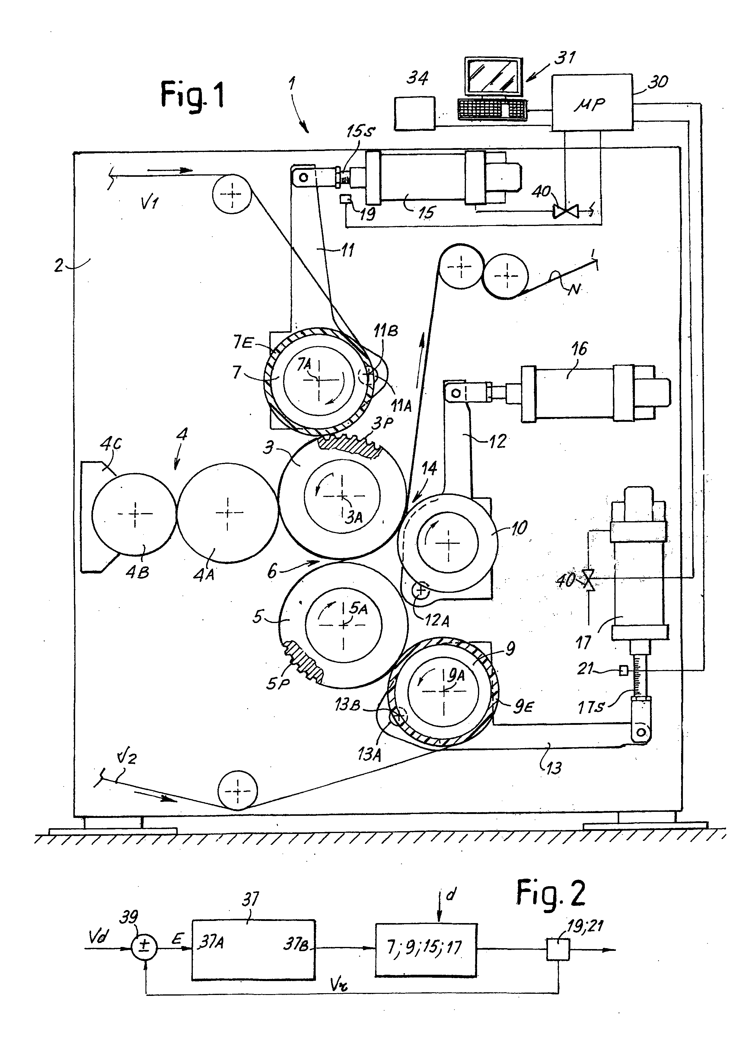
[0033]There will be described below an application of the present invention to a complex embossing-laminating unit, with two embossing rollers and two pressure rollers, as well as one laminating roller. However, it must be understood that the invention may also be advantageously embodied in simpler or other types of embossing units. For example, advantages may also derive from the application of the invention to simple embossing machines having only one embossing roller and one pressure roller.

[0034]With reference to FIG. 1, in one possible embodiment the embossing unit, indicated as a whole with 1, comprises a first embossing roller 3 and a second embossing roller 5, cooperating respectively with a first pressure roller 7 and a second pressure roller 9. Each embossing roller 3, 5 has, on its cylindrical surface, a plurality of protuberances 3P, 5P, while each pressure roller 7, 9 comprises a cylindrical surface coated with a layer of elastically yielding material 7E and 9E. In the ...


PUM

PropertyMeasurementUnit
Pressureaaaaaaaaaa

Abstract

An embossing unit including at least one embossing roller, provided with embossing protrusions or recesses on a cylindrical surface; at least one pressure roller coated with an elastically yielding material and cooperating with the embossing roller; at least one actuator that presses the pressure roller and the embossing roller against each other; an automatic position adjustment system, to adjust the reciprocal position of the pressure roller and the embossing roller.

Description

TECHNICAL FIELD[0001]The present invention relates to machines for converting continuous web materials. In particular, the invention relates to enhancements to so-called embossing units for processing paper or other materials, particularly cellulose materials. The invention also relates to embossing methods.BACKGROUND OF THE INVENTION[0002]In the field of processing sheets or webs of paper or similar materials, the term embossing refers to a process of permanent deformation of the web material, which causes the production of raised zones or protuberances with a technical-functional or an aesthetic function, or a dual technical-functional and aesthetic function.[0003]For example, in the processing of so-called “tissue” paper for the production of kitchen towels, toilet paper, paper handkerchiefs and napkins, or other similar items, embossing is used both to decorate the cellulose web material, and to impart particular technical characteristics to the material, for example an apparent...

Claims


Application Information

Patent Timeline
IPC IPC(8): B31F1/07
CPCB31F1/07B31F2201/0787B31F2201/0779B31F2201/0753
Inventor RICCI, MAUROBOSCHI, LEONARDO
Owner FABIO PERINI SPA
Why Eureka
Try Eureka