Linear vibrator

a linear vibrator and vibrating device technology, applied in mechanical vibration separation, dynamo-electric machines, electrical apparatus, etc., can solve the problems of small vibration power, damage to elastic units, linear vibrators becoming voluminous, etc., and achieve the effect of greatly increasing vibration force and reducing linear vibrator siz

Inactive Publication Date: 2013-04-25
EM TECHNOLOGY CO LTD
View PDF11 Cites 72 Cited by
  • Summary
  • Abstract
  • Description
  • Claims
  • Application Information

AI Technical Summary

Benefits of technology

[0010]The present disclosure is to provide a linear vibrator configured to greatly decrease size of the linear vibrator by generating vibration to a horizontal direction but to greatly increase vibration force.
[0011]Furthermore, the present disclosure is to provide a linear vibrator configured to inhibit destruction and damage of an elastic unit by forcibly stopping a vibrator in a case the vibrator is deviated from an effective vibration section by an outside shock during generation of vibration to a horizontal direction.
[0013]As apparent from the foregoing, there is an advantageous effect in the linear vibrator thus configured according to the present disclosure in that size of the linear vibrator can be greatly decreased by generating vibration to a horizontal direction while vibration force can be greatly increased.
[0014]Another advantageous effect is that an elastic unit can be inhibited from being destructed or damaged by forcibly stopping a vibrator, in a case the vibrator is deviated from an effective vibration section by an outside shock during generation of vibration to a horizontal direction.

Problems solved by technology

However, the conventional linear vibrator has a disadvantage in that, when the vibration is generated by the vertical movement of the vibrator relative to the stator, vibration power is small and the linear vibrator comes to be voluminous.
However, the conventional linear vibrator horizontally vibrating to generate vibration suffers from a disadvantage in that a large stress is applied to an elastic unit vibrating a vibrator to easily destroy or damage the elastic unit in a case a shock is applied from outside to a vibrating direction of the linear vibrator.

Method used


Image

  • Linear vibrator
  • Linear vibrator
  • Linear vibrator

Examples


first exemplary embodiment

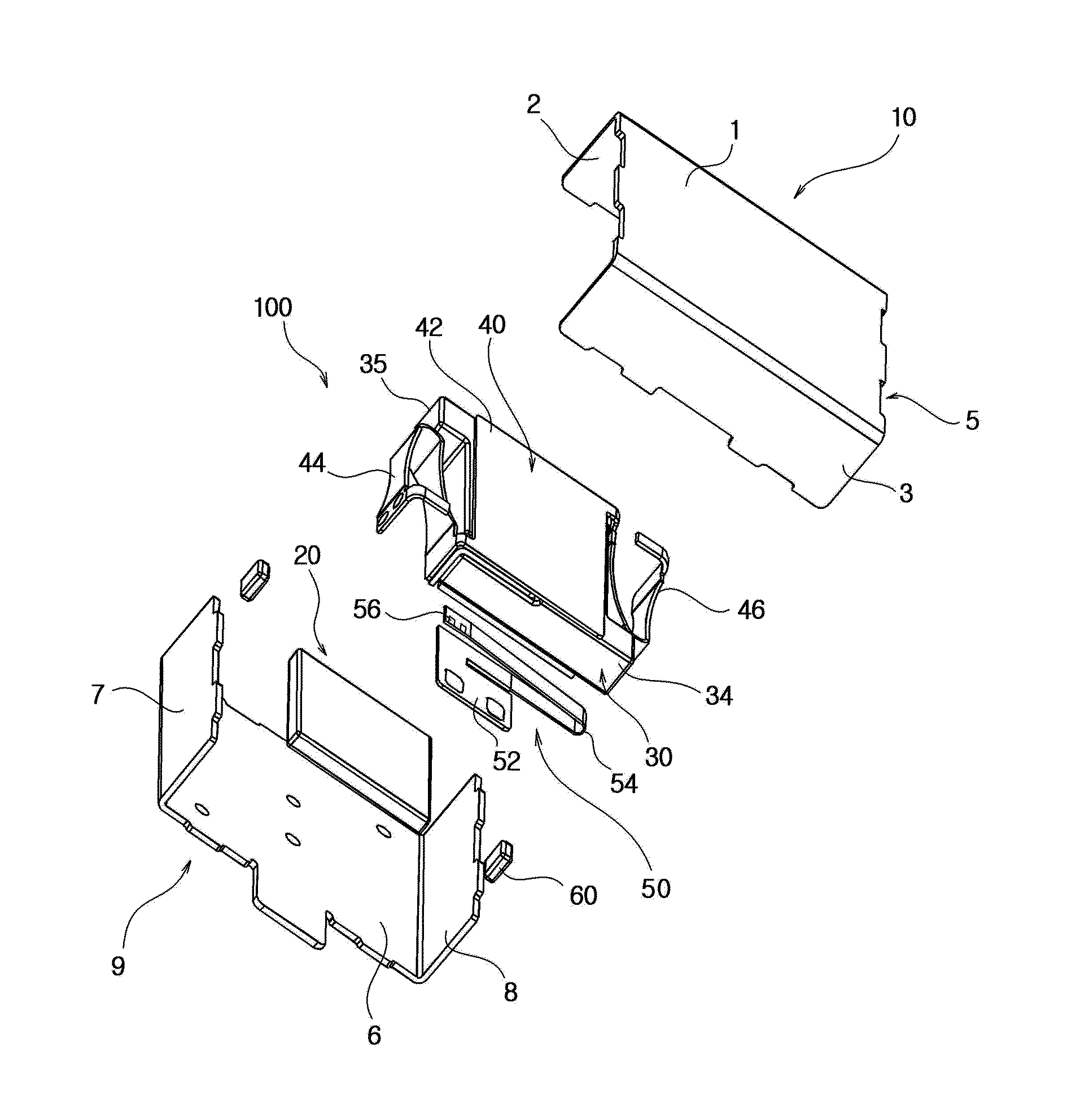
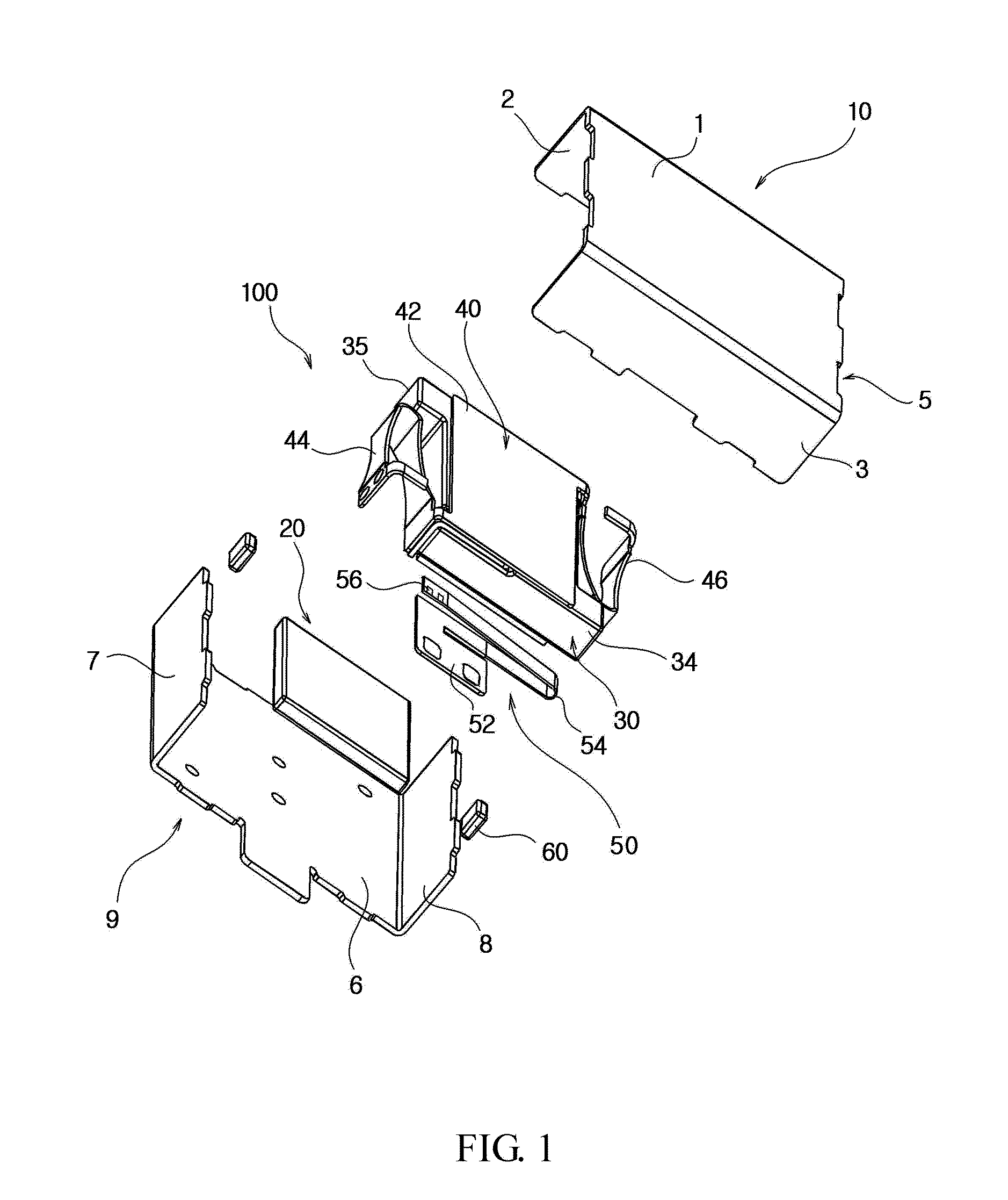
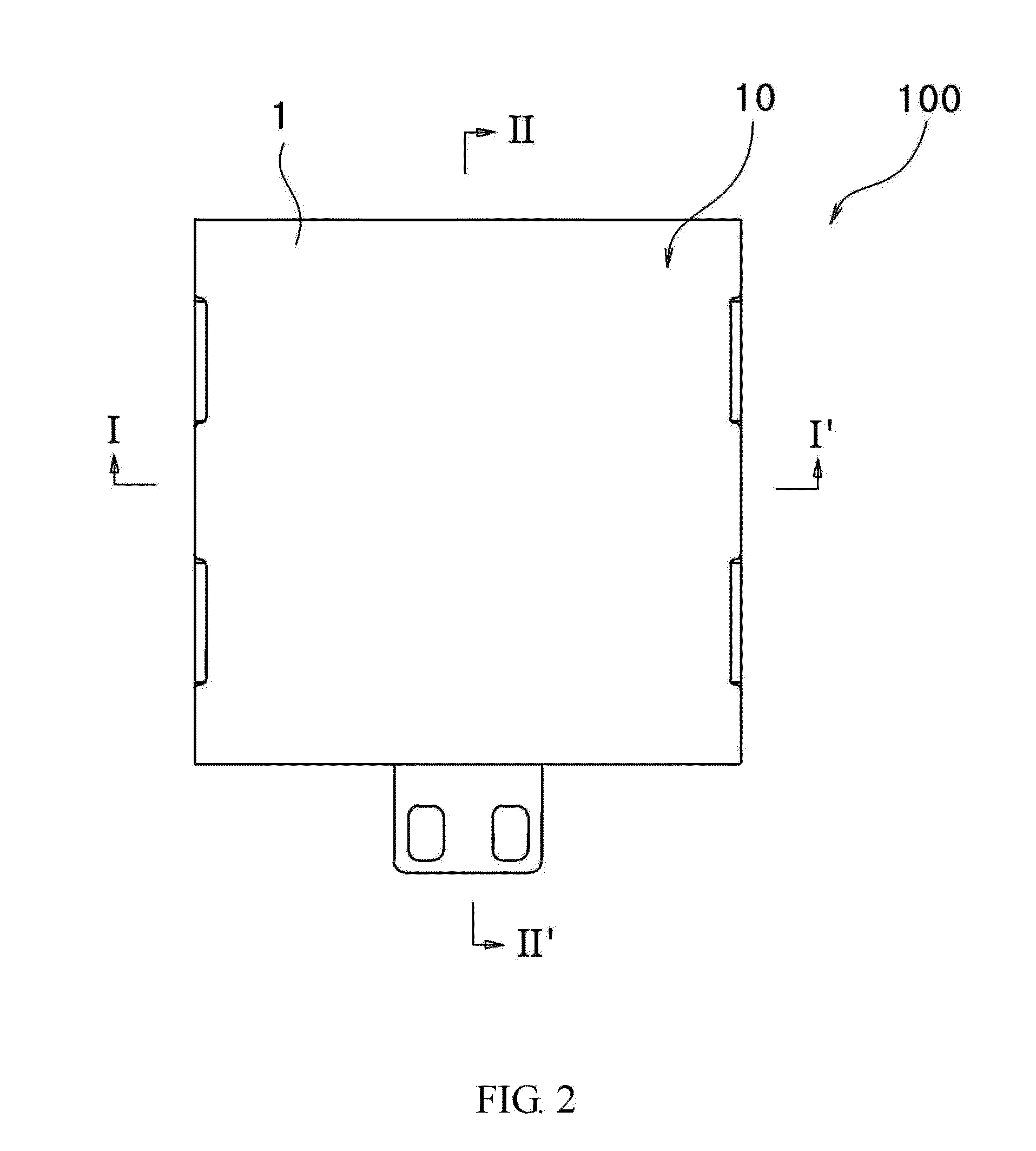
[0035]FIG. 1 is an exploded perspective view illustrating a linear vibrator according to a first exemplary embodiment of the present disclosure, FIG. 2 is a plane view illustrating an assembled linear vibrator of FIG. 1, FIG. 3 is a cross-sectional view taken along line ‘I-I’ of FIG. 2, FIG. 4 is a cross-sectional view taken along line ‘II-II’ of FIG. 2, FIG. 5 is a perspective extract view illustrating a bottom case, a magnet and a flexible circuit substrate of FIG. 1, FIG. 6 is a perspective view illustrating a flexible circuit substrate of FIG. 1, and FIG. 7 is an exploded perspective view illustrating a second driving unit of the linear vibrator of FIG. 1.

[0036]Referring to FIGS. 1 to 7, a linear vibrator (90) includes a case (10) providing an inner space, a first driving unit (20) arranged inside the case (10), a second driving unit (30) arranged inside the case to be driven to a horizontal direction relative to the first driving unit (20), and an elastic unit (40) elastically ...

second exemplary embodiment

[0061]FIG. 8 is a plane view illustrating a linear vibrator according to a second exemplary embodiment of the present disclosure, and FIG. 9 is a cross-sectional view taken along line ‘III-III’ of FIG. 8.

[0062]Referring to FIGS. 8 and 9, a linear vibrator (600) includes a case (100), a first driving unit (200), a second driving unit (300) and an elastic unit (330). FIG. 10 is a plane view illustrating a bottom case of FIG. 9, and FIG. 11 is a perspective view of FIG. 10.

[0063]Referring to FIGS. 8 to 10, the case (100) includes a bottom case (110) and an upper case (120). The case (100) in the exemplary embodiment of the present disclosure includes a stopper (described later) inhibiting the second driving unit (300) from exceeding a normal moving range. The bottom case (110) includes a floor plate (1110 and lateral plates (112, 113) vertically bent or vertically bent relative to the floor plate (111) from both edges opposite to the floor plate (111).

[0064]Referring to FIG. 9, the upp...


PUM


Abstract

A linear vibrator is disclosed, the linear vibrator including a case providing an inner space, a first driving unit arranged inside the case, a second driving unit arranged inside the case to be driven to a horizontal direction relative to the first driving unit, and an elastic unit arranged on lateral surfaces opposite the second driving unit to elastically support the second driving unit inside the case.

Description

CROSS-REFERENCE TO RELATED APPLICATIONS[0001]This application claims the benefit under 35 U.S.C. §119 of Korean Patent Application Nos. 10-2011-0108590, filed Oct. 24, 2011, and 10-2012-0014155, filed Feb. 13, 2012, which are hereby incorporated by reference in their entirety.BACKGROUND[0002]1. Field of the Disclosure[0003]The present disclosure relates to a linear vibrator.[0004]2. Description of Related Art[0005]Generally, a linear vibrator is employed for generating vibration in electronic appliances, such as mobile phones, smart phones, gaming machines, portable information terminals, smart pads and game controllers, using electromagnetic force between a magnet and a coil.[0006]A conventional linear vibrator is configured such that when a current is applied to a coil, operation of vibrator is initiated by electromagnetic force formed between the coil and the magnet to vertically vibrate the vibrator in association with elasticity of a spring relative to a stator.[0007]However, t...

Claims


Application Information

Patent Timeline
Patent Type & Authority Applications(United States)
IPC IPC(8): H02K33/00
CPCB06B1/045
Inventor PARK, YOUNG IL
Owner EM TECHNOLOGY CO LTD
Why Eureka
Try Eureka