Flip-top preform for blow molding

Active Publication Date: 2013-05-02
TRICORBRAUN
View PDF5 Cites 7 Cited by
  • Summary
  • Abstract
  • Description
  • Claims
  • Application Information

AI Technical Summary

Benefits of technology

[0007]Another aspect of the invention pertains to a preform for blow molding plasti

Problems solved by technology

While this method of assembly is widely used, it does require multiple manufacturing steps and generally requires the use of a greater amount of plastic materia

Method used


Image

  • Flip-top preform for blow molding
  • Flip-top preform for blow molding
  • Flip-top preform for blow molding

Examples


Example

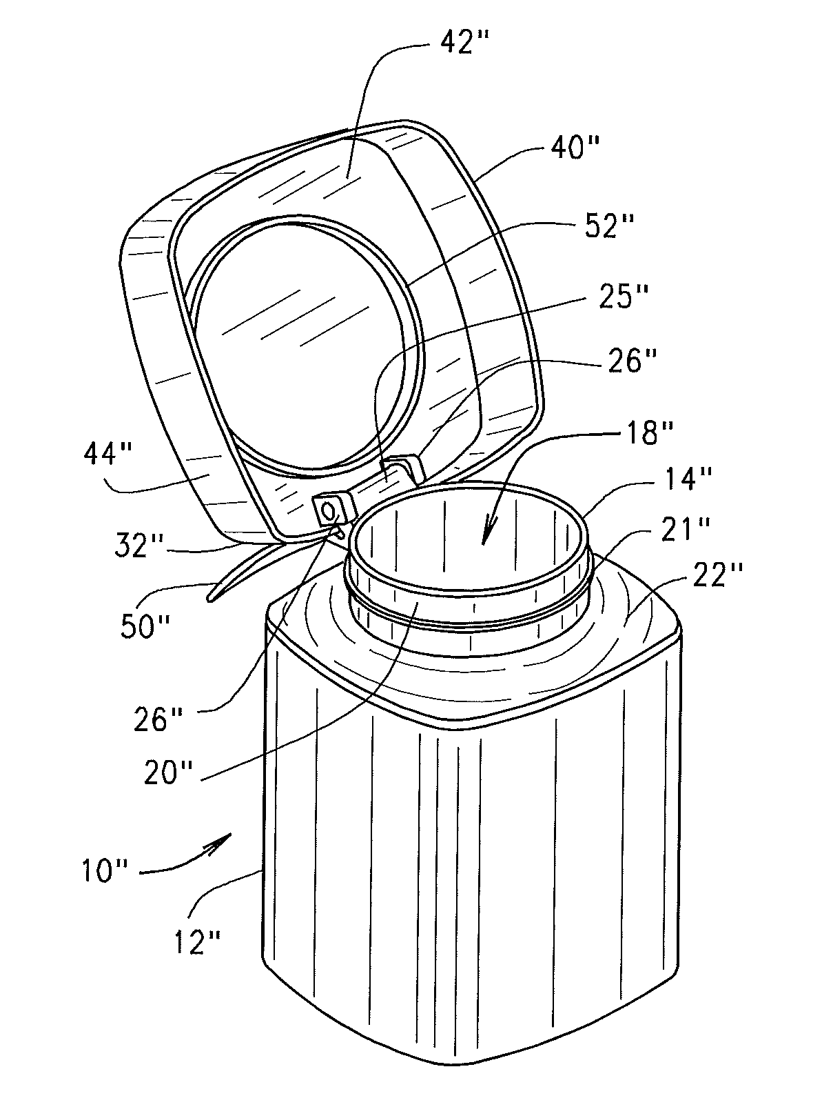
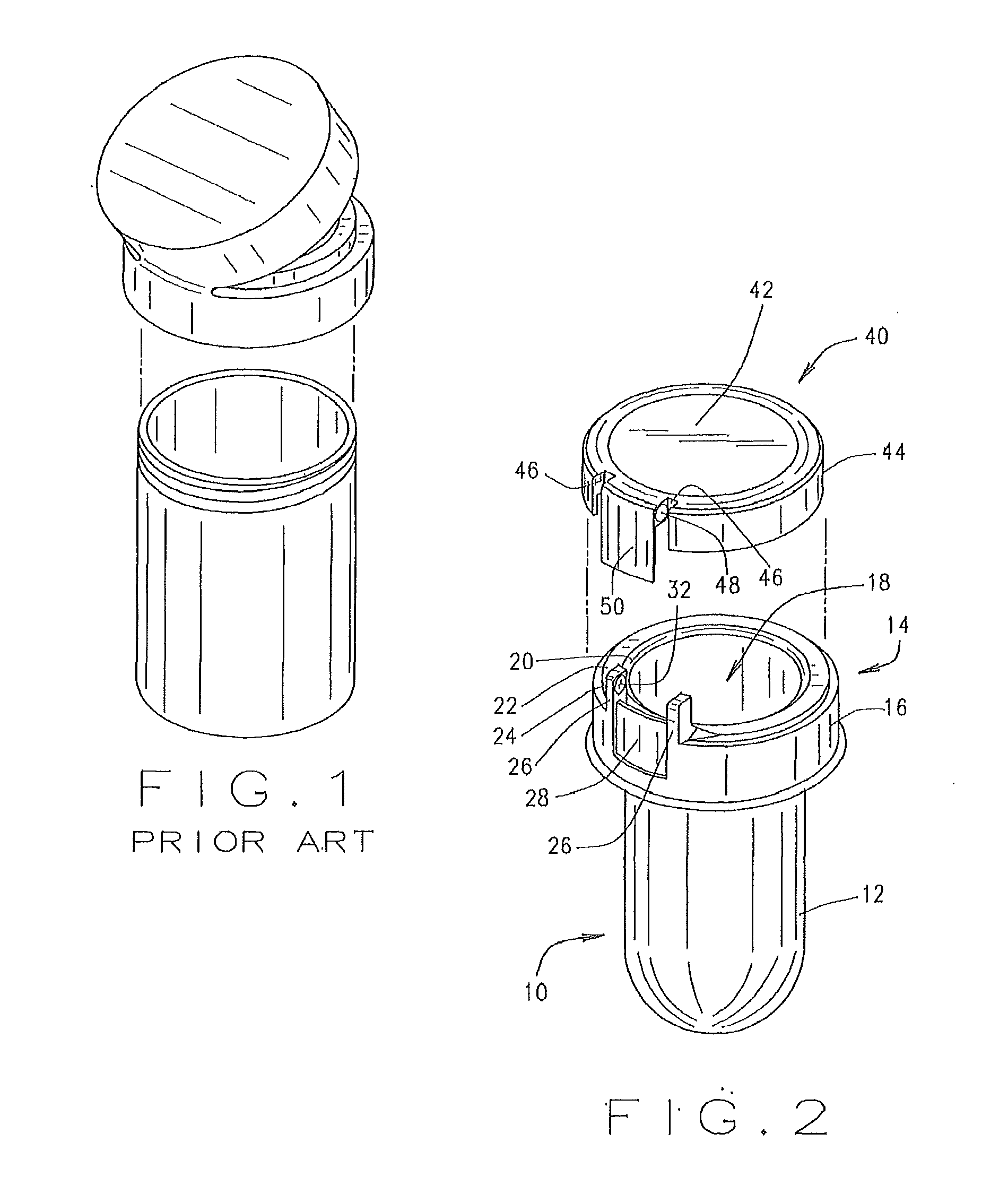
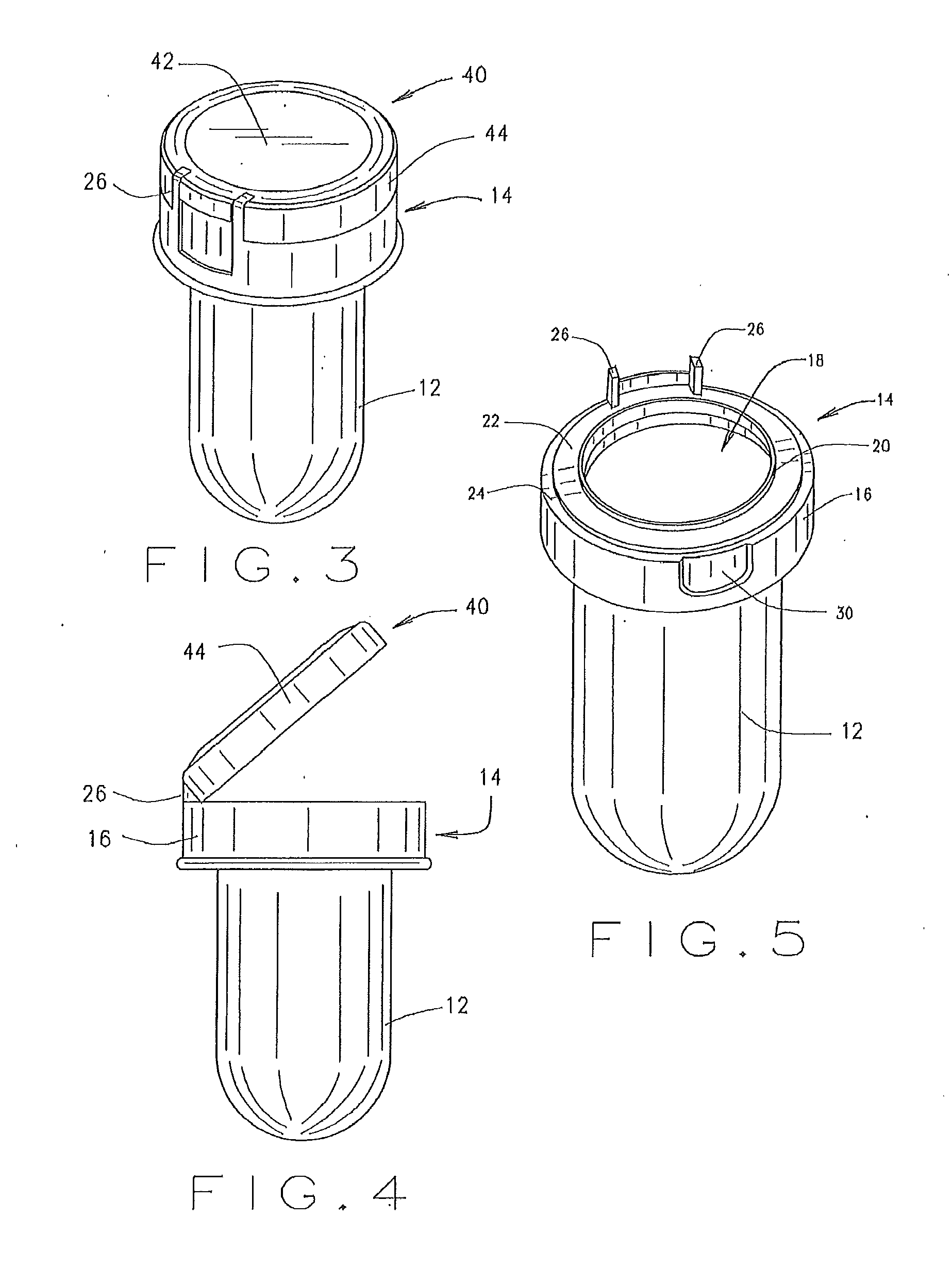
[0027]FIGS. 2-5 illustrate an embodiment of a preform 10 according to a first embodiment of the present invention. The preform 10 includes a container portion 12 and a closure base portion 14. The container portion 12 is tube-shaped and hollow in order to be compatible with existing injection blow molding equipment. The container portion 12 and closure base portion 14 are co-molded together.

[0028]The closure base portion 14 is the lower half of a flip-top closure. The closure base portion has an outer skirt 16 and a central opening 18 that communicates with the hollow interior of the container portion 12 of the preform 10. Surrounding the central opening 18 is a slightly upwardly extending collar 20. Surrounding the collar 20 is a generally flat, first horizontal surface 22. Outside of this first horizontal surface 22 is a second surface 24 that lies slightly below the level of the first surface 22. The closure base portion 14 also includes a matching pair of hinge members 26 extend...


PUM

PropertyMeasurementUnit
Angleaaaaaaaaaa

Abstract

A preform for blow molding a plastic container, and the resulting container, with a flip-top closure includes a container portion and a flip-top closure base portion integrally molded with the container portion. The flip-top closure base portion includes an integrally molded first hinge structure for connecting the flip-top closure base portion to a second hinge structure on a flip-top closure top to create the flip-top closure for the container.

Description

CROSS REFERENCE[0001]This application is a continuation-in-part of and claims priority to U.S. application Ser. No. 13 / 281,625 filed Oct. 26, 2011, which in turn claims priority to U.S. Provisional Patent Application No. 61 / 408,360, filed Oct. 29, 2010.TECHNICAL FIELD OF THE INVENTION[0002]The present invention relates generally to the field of blow molding plastic containers and, more particularly, to an improved preform for blow molding plastic containers.BACKGROUND OF THE INVENTION[0003]Injection blow molding is a commonly used manufacturing process for producing hollow plastic parts from thermoplastic material. Injection blow molding can be used to produce plastic containers, most frequently small medical and single serve bottles. In general, the blow molding process involves melting down a thermoplastic material and forming it into a parison or preform. The perform is typically a tube-like piece of plastic with a hole in one end to accommodate the introduction of compressed air...

Claims


Application Information

Patent Timeline
IPC IPC(8): B65D17/34B32B1/02B29C49/42B65D43/16
CPCB29L2031/712Y10T428/1352B29B2911/14013B29B2911/14426B29B2911/14433B29B2911/1446B29B2911/1452B29B2911/14573B29C49/42B32B1/02B65D43/169B29B11/14B29C49/06B65D43/164B29B11/08B29C2949/20B29C2949/0771B29C2949/0772B29C2949/0776B29C2949/0792B29C2949/08B29C49/071B29C2949/0715
Inventor SAWICKI, CRAIG R.
Owner TRICORBRAUN
Why Eureka
Try Eureka