
Printed circuit board testing device

a testing device and printed circuit board technology, applied in the direction of measurement devices, printed circuit testing, instruments, etc., can solve the problems of requiring a long r&d process, testing devices cannot perform electrical tests on different printed circuit boards, and the use of dedicated circuits or components for electrical signals

Inactive Publication Date: 2013-05-02
ASKEY TECH JIANGSU +1
View PDF2 Cites 53 Cited by
  • Summary
  • Abstract
  • Description
  • Claims
  • Application Information

AI Technical Summary

Benefits of technology

The present invention is a printed circuit board testing device that has a plurality of preset electrical functions, allowing a test worker to select the appropriate test to test the electrical functions of the printed circuit board without having to make a new dedicated testing device. This simplifies the process of testing the printed circuit board and reduces the time and effort required for the test.

Problems solved by technology

However, the technical solution that involves generating the electrical signal source by a dedicated circuit or component is only applicable to the testing environment of a specific printed circuit board under test.
Hence, the testing device cannot perform an electrical test on different printed circuit boards.
However, designing the testing device anew has drawbacks, that is, it requires a lengthy R&D process and incurs much production costs.

Method used


Image

  • Printed circuit board testing device
  • Printed circuit board testing device
  • Printed circuit board testing device

Examples


Embodiment Construction

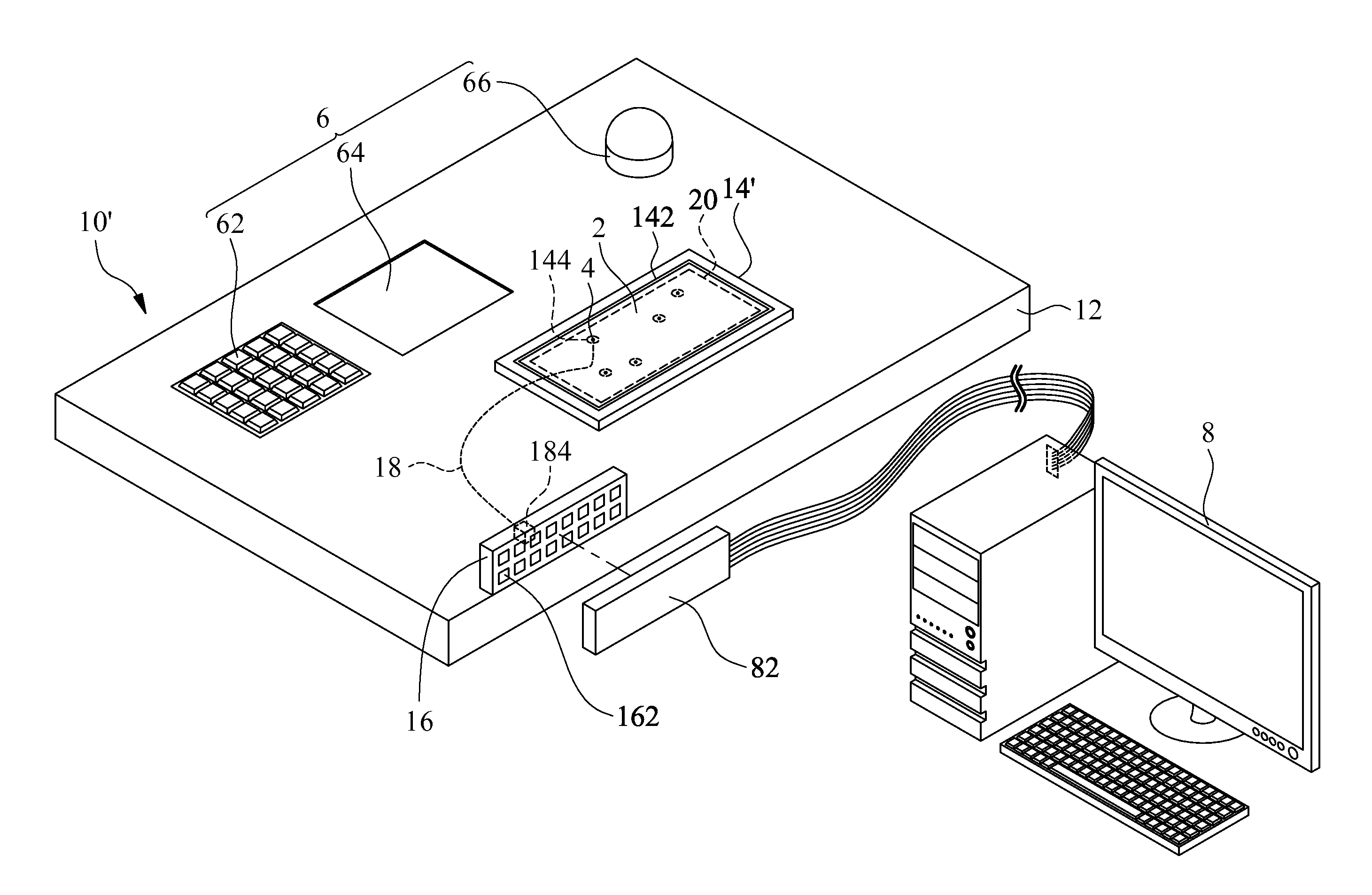
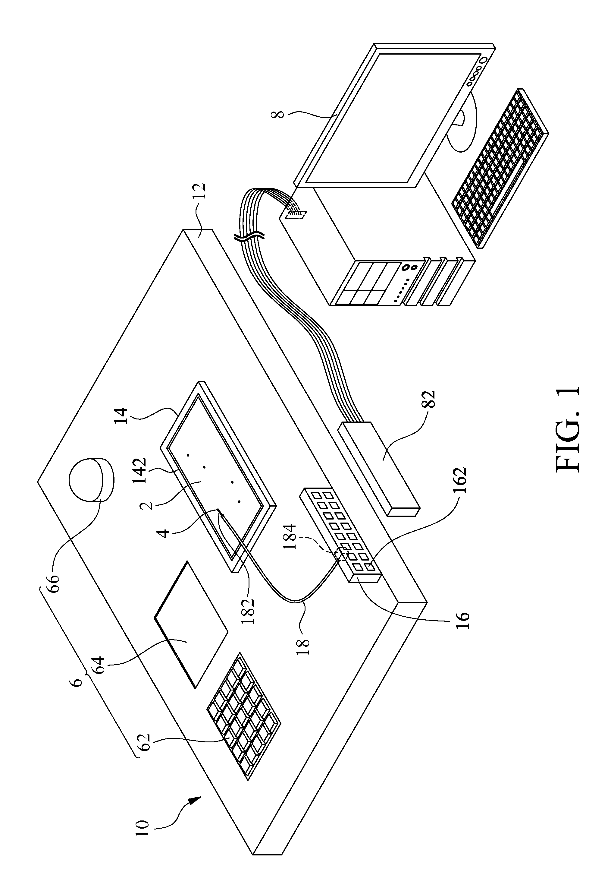
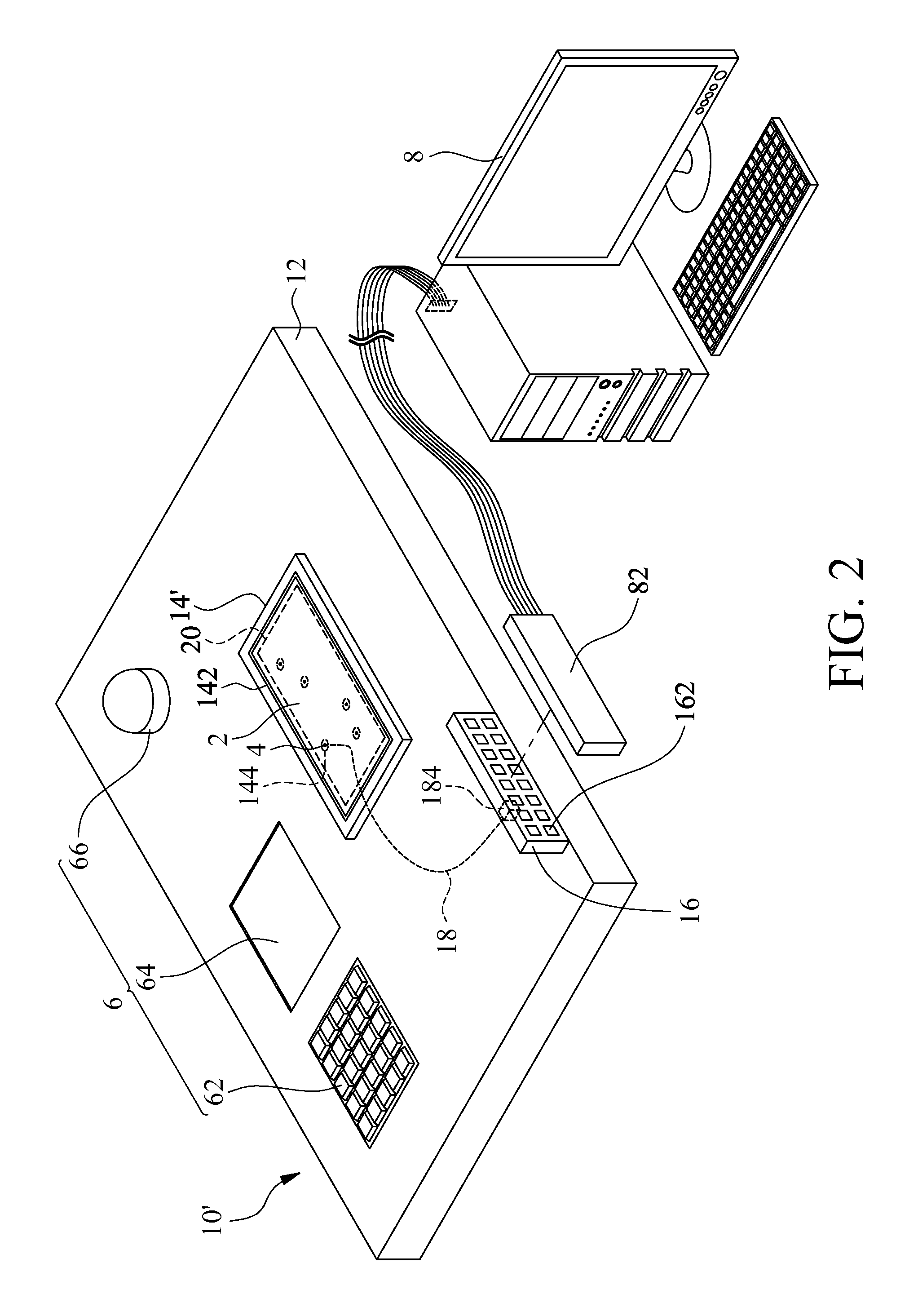
[0016]Referring to FIG. 1, there is shown a structural schematic view of a printed circuit board testing device 10 according to the first embodiment of the present invention. As shown in FIG. 1, the printed circuit board testing device 10 performs an electrical test on a printed circuit board 2. The electrical test is aimed at testing electrical features and is a voltage test, a data transmission test, a sound source test, or a display signal test. The printed circuit board 2 has a plurality of test contacts 4. The test contacts 4 are connected to an electronic device 6, such as a keyboard 62, a monitor 64, and / or a speaker 66, through the circuit layout on the printed circuit board 2.

[0017]The printed circuit board testing device 10 comprises a test platform 12, a positioning unit 14, an electrical connection unit 16, and a detecting unit 18. The positioning unit 14, the electrical connection unit 16, and the detecting unit 18 are disposed at the test platform 12.

[0018]The position...


PUM


Abstract

A printed circuit board testing device for performing an electrical test on a printed circuit board having test contacts includes a test platform, a positioning unit, an electrical connection unit, and a detecting unit. The positioning unit is disposed on the test platform and adapted to receive the printed circuit board. The electrical connection unit is disposed on the test platform and has a plurality of preset electrical functions. The electrical test specific to the test contacts is performed on the test contacts by the detecting unit connected to the test contacts and the electrical connection unit and based on the preset electrical functions.

Description

CROSS-REFERENCE TO RELATED APPLICATION[0001]This non-provisional application claims priority under 35 U.S.C. §119(a) on Patent Application No(s). 100139338 filed in Taiwan, R.O.C. on Oct. 28, 2011, the entire contents of which are hereby incorporated by reference.FIELD OF TECHNOLOGY[0002]The present invention relates to printed circuit board testing devices, and more particularly, to a printed circuit board testing device for performing a related electrical test on a printed circuit board having test contacts.BACKGROUND[0003]According to the prior art, upon completion of a circuit layout defining process performed on a printed circuit board, it is necessary to perform an electrical test on the circuit layout on the printed circuit board for verifying whether the circuit layout enables good electrical connection efficiently.[0004]Regarding the issue of testing a printed circuit board, related testing devices for use in testing printed circuit boards are used to being developed in acc...

Claims


Application Information

Patent Timeline
Patent Type & Authority Applications(United States)
IPC IPC(8): G01R31/20
CPCG01R31/2808
Inventor LIU, CHENG-TEHSIEH, CHING-FENG
Owner ASKEY TECH JIANGSU
Learn More