Medical image processing apparatus, method and program

a medical image and processing apparatus technology, applied in the field of graph structure construction techniques, can solve the problems of incorrect connection of linear structure elements to each other, and achieve the effect of high accuracy and extraction

Inactive Publication Date: 2013-05-02
FUJIFILM CORP
View PDF1 Cites 17 Cited by
  • Summary
  • Abstract
  • Description
  • Claims
  • Application Information

AI Technical Summary

Benefits of technology

[0031]Second, plural linear structures representing fragments of bronchi are extracted by analyzing a local density structure in a neighborhood of each point in the three-dimensional medical image. As described above, a small diameter portion of the bronchi in the image may be interrupted. However, since this second extraction technique can handle the bronchi as a set of fragmentary linear structures, highly accurate extraction is possible.
[0032]Further, different cost functions are used for a first segment connecting the node constituting the graph structure representing the continuous region of the bronchi and the node representing the linear structures representing fragments of the bronchi and a second segment connecting the nodes representing the linear structures representing fragments of the bronchi to each other. Further, the cost function in the first segment is defined in such a manner that the first segment is more likely to be connected as a change in voxel values is smaller among first segments. Further, a graph structure of the bronchi is reconstructed by using this cost function. Therefore, it is possible to appropriately connect a large diameter portion of the bronchi extracted by using the first extraction method and a small diameter portion of the bronchi extracted by using the second extraction method.
[0033]Accordingly, a graph structure of bronchi in a three-dimensional medical image is constructed, at higher accuracy.

Problems solved by technology

Therefore, there is a risk that the linear structure elements are not correctly connected to each other.

Method used


Image

  • Medical image processing apparatus, method and program
  • Medical image processing apparatus, method and program
  • Medical image processing apparatus, method and program

Examples


Embodiment Construction

[0049]Hereinafter, a medical image diagnosis system to which a medical image processing apparatus according to an embodiment of the present invention has been introduced will be described.

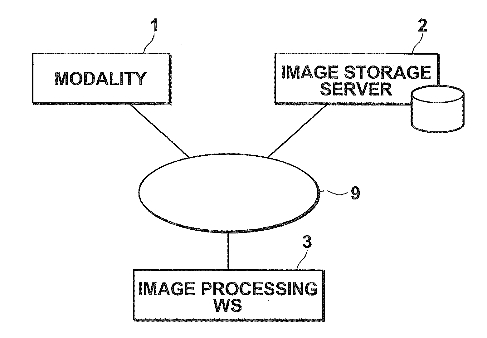
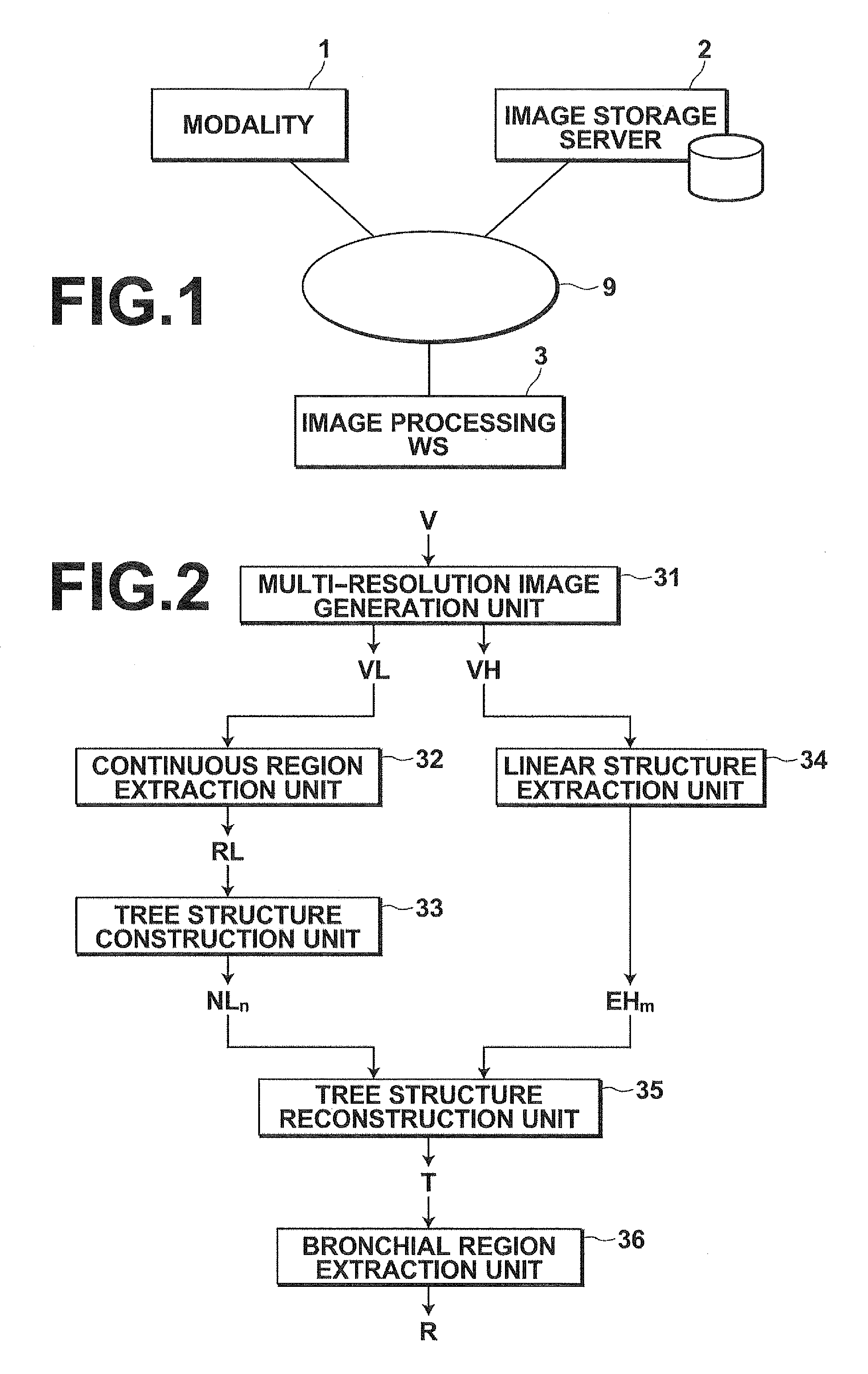
[0050]FIG. 1 is a schematic diagram illustrating the hardware configuration of this medical image diagnosis system. In this system, a modality 1, an image storage server 2, and an image processing workstation 3 are connected to each other through a network 9 in such a manner that they can communicate with each other, as illustrated in FIG. 1.

[0051]The modality 1 includes an apparatus that generates image data of a three-dimensional medical image representing an examination target region of a subject to be examined by imaging the region. The apparatus attaches supplementary information defined by DICOM (Digital Imaging and Communications in Medicine) standard to the image data, and outputs the image data, as image information. In the present embodiment, a CT is used as the modality 1, and a case in ...


PUM


Abstract

A continuous-region-extraction unit extracts a continuous-region having a voxel value corresponding to an air-region in bronchi from a three-dimensional-medical-image. A tree-structure-construction unit constructs a tree-structure corresponding to the continuous-region. A linear-structure-extraction unit extracts plural linear-structures representing fragments of small-bronchi by analyzing a local density structure in a neighborhood of each point in the three-dimensional-medical-image. A tree-structure-reconstruction unit reconstructs a graph-structure representing the whole bronchi by connecting a node constituting the graph-structure of large-bronchi and a node representing the linear-structures of small-bronchi. At this time, different cost functions are used for a segment connecting the node of the large-bronchi and the node representing the linear-structures of the small-bronchi and a segment connecting the nodes representing the linear-structures to each other. The cost function in the former segment is defined in such a manner that the segment is more likely to be connected as a change in voxel values is smaller.

Description

BACKGROUND OF THE INVENTION[0001]1. Field of the Invention[0002]The present invention relates to a technique for constructing a graph structure representing a tubular structure in a three-dimensional medical image.[0003]2. Description of the Related Art[0004]Lung cancers are a disease in which a survival rate sharply drops as the stage of the disease progresses. Therefore, early detection and early treatment of lung cancers are extremely important. For example, when a shadow of a suspicious tumor or the like is found in a simple X-ray image of a chest, a CT image or the like, precise examinations are necessary to judge whether the suspicious tumor is a tumor. If the suspicious tumor is a tumor, it is necessary to judge whether the tumor is benign or malignant. In judging whether the tumor is benign or malignant, a pathology examination is performed by removing a part of the tumor by a bronchial endoscope. In this examination, it is important to more speedily and more accurately move...

Claims


Application Information

Patent Timeline
Patent Type & Authority Applications(United States)
IPC IPC(8): G06T7/00
CPCG06T3/0037G06T7/0079G06T7/0012G06T7/10
Inventor INOUE, TSUTOMU
Owner FUJIFILM CORP
Why Eureka
Try Eureka