
Image forming apparatus capable of optimally performing density fluctuation correction

a technology of density fluctuation and image forming, which is applied in the direction of electrographic process apparatus, instruments, optics, etc., can solve the problems of inability to completely prevent density fluctuation, difficult to keep the relative positions of the photoreceptor and the developing roller constant, and inability to correct density fluctuation

Inactive Publication Date: 2013-05-02
RICOH KK
View PDF4 Cites 29 Cited by
  • Summary
  • Abstract
  • Description
  • Claims
  • Application Information

AI Technical Summary

Benefits of technology

The present invention is an improvement to image forming apparatuses that helps reduce density fluctuations caused by the rotation of the image carrier. These fluctuations can occur even if the image carrier and developing roller are not perfectly aligned. The new improvement helps to produce a more consistent and high-quality image.

Problems solved by technology

Fluctuation in the density within one page has various causes, such as unstable charge due to uneven charging; fluctuation of exposure by the exposure unit; variations in the sensitivity of the photoreceptor; variations in the resistance of a developing roller; fluctuation in the charge of the toner; and variations in the transferring of a transfer roller.
However, when a print job is again executed after another print job has finished and the relative positions of the photoreceptor and the developing roller have changed, because the density fluctuation profile has changed, the density fluctuation cannot be corrected.
Accordingly, it is difficult to keep the relative positions of the photoreceptor and the developing roller constant.
As a result, the density fluctuation cannot be prevented completely by simply measuring the density fluctuation and adjusting it with the rotational cycle of the photoreceptor, and a satisfactory correction effect cannot be obtained.

Method used


Image

  • Image forming apparatus capable of optimally performing density fluctuation correction
  • Image forming apparatus capable of optimally performing density fluctuation correction
  • Image forming apparatus capable of optimally performing density fluctuation correction

Examples


first embodiment

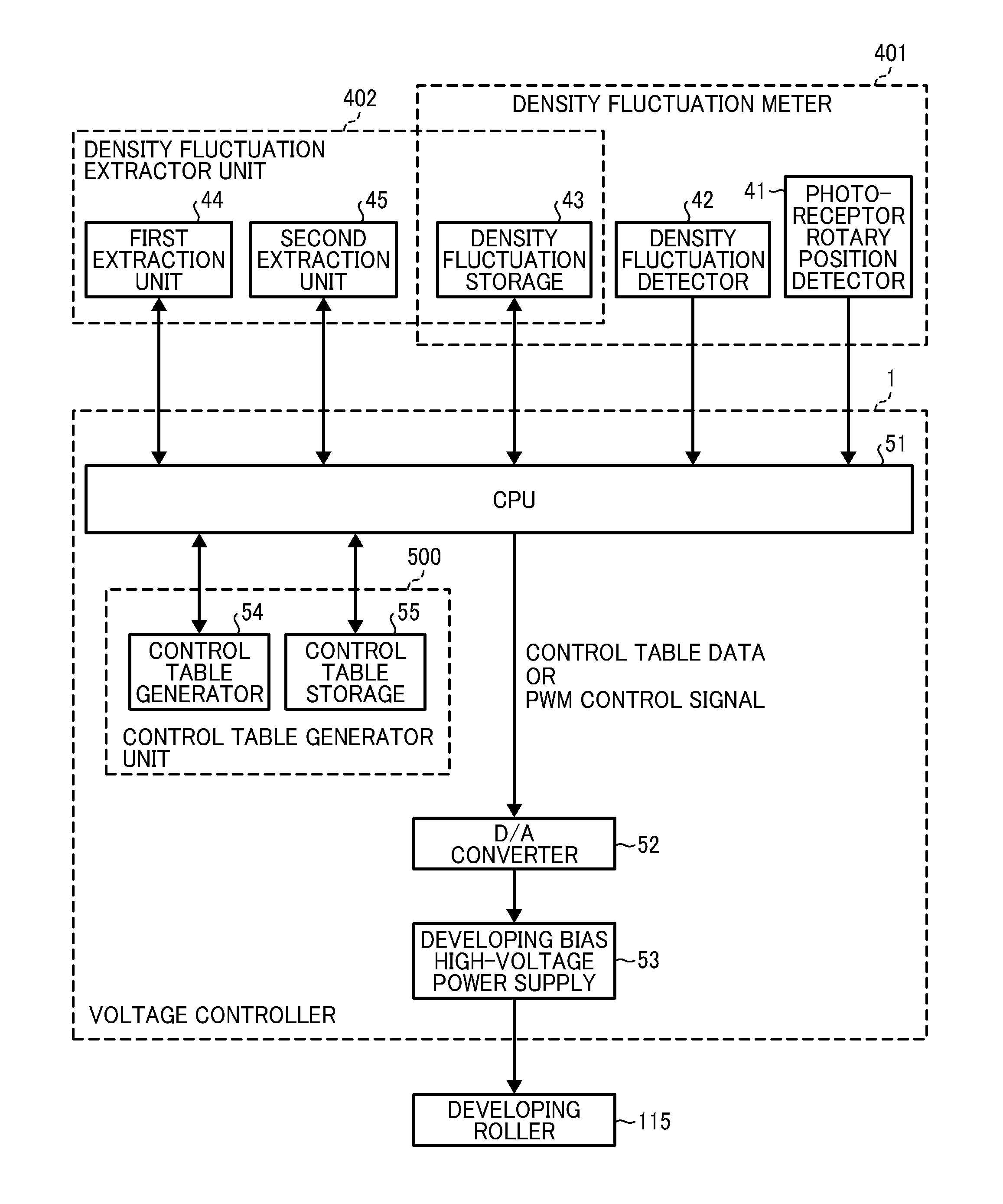
[0065]FIG. 6 is a block diagram illustrating a structure of a unit for executing density fluctuation correction according to the present invention.

[0066]In FIG. 6, the density fluctuation correction means includes a density fluctuation meter 401 to measure the density fluctuation of the photoreceptor in the rotation direction and a density fluctuation extractor unit 402 to extract the density fluctuation of the cyclic components due to the rotary cycle of the photoreceptor.

[0067]The density fluctuation meter 401 includes a rotary position detector 41 to detect a reference rotary position of the photoreceptor; a density fluctuation detector 42 to detect a density fluctuation in the rotary direction of the photoreceptor; and a density fluctuation storage 43 to store the detected density fluctuation.

[0068]The density fluctuation extractor 402 includes a first extraction unit 44 to extract a density fluctuation of each rotary cycle of the photoreceptor from the stored density fluctuatio...

second embodiment

[0080]FIG. 8 is a block diagram illustrating a structure of a second embodiment for executing a density fluctuation correction.

[0081]In FIG. 8, the density fluctuation correction means includes the density fluctuation meter 401 to measure the density fluctuation of the photoreceptor in the rotation direction, the density fluctuation extractor unit 402 to extract an average density fluctuation due to the rotary cycle, and a change controller 46 to change a relative position of the photoreceptor and the developing roller.

[0082]The density fluctuation meter 401 is configured as in the first embodiment described above and includes the photoreceptor reference rotary position detector 41, the density fluctuation detector 42 to detect the density fluctuation in the rotation direction of the photoreceptor, and the density fluctuation storage 43 to store the detected density fluctuation.

[0083]The density fluctuation extractor unit 402 includes a density fluctuation extractor 44B to extract d...

third embodiment

[0095]FIG. 10 is a block diagram illustrating a structure of a third embodiment for executing a density fluctuation correction.

[0096]In FIG. 10, the density fluctuation correction means includes a density fluctuation meter 401 to measure the density fluctuation of the photoreceptor in the rotation direction and a density fluctuation extractor unit 402 to extract the density fluctuation of the cyclic components due to the rotary cycle of the photoreceptor.

[0097]The density fluctuation meter 401 includes a rotary position detector 41 to detect a reference rotary position of the photoreceptor; a density fluctuation detector 42 to detect a density fluctuation in the rotary direction of the photoreceptor; and a density fluctuation storage 43 to store the detected density fluctuation.

[0098]The density fluctuation extractor unit 402 includes a density fluctuation extractor 44C to extract a density fluctuation of the photoreceptor rotary cycle; an analyzer 49 to extract an amplitude and a p...


PUM


Abstract

An image forming apparatus includes an image carrier; a developing device; a transfer device; and a fixing device. An electrostatic latent image formed on the image carrier is rendered visible as a toner image by depositing the toner by the developing device, and the toner image is transferred by the transfer device and fixed onto a recording medium by the fixing device and output. The apparatus further includes a density fluctuation meter including a rotary position detector, a density fluctuation detector, and a density fluctuation storage; a density fluctuation extractor unit including a first extractor, a second extractor, and a density fluctuation storage; and a control table generator unit including a control table generator and a control table storage, so that based on the control table stored in the control table storage, the voltage to be applied to the developing device is controlled and the toner image is output.

Description

CROSS-REFERENCE TO RELATED APPLICATION[0001]The present application claims priority from Japanese patent application number 2011-241007, filed on Nov. 2, 2011, the entire disclosure of which is incorporated by reference herein.BACKGROUND OF THE INVENTION[0002]1. Field of the Invention[0003]The present invention relates to an image forming apparatus employing an electrophotographic method, such as a copier, a printer, or a facsimile machine, and in particular relates to an image forming apparatus capable of optimally correcting density fluctuations in an output image.[0004]2. Description of the Related Art[0005]An image forming apparatus employing an electrophotographic method forms an image by uniformly charging a photoreceptor or an image carrier by a charger, after which a latent image is formed on the photoreceptor by an exposure unit based on input image data and toner is adhered on the latent image by a developing device to thus render it a visual image. Such image forming appa...

Claims


Application Information

Patent Timeline
IPC IPC(8): G03G15/06
CPCG03G15/0189G03G2215/0164G03G2215/0129G03G15/5058
Inventor SUZUKI, SHINGOKANEKO, SATOSHIKUDO, KOICHIHIRAI, SHUJIKATO, SHINJIYAMANE, JUN
Owner RICOH KK
Features
  • Generate Ideas
  • Intellectual Property
  • Life Sciences
  • Materials
  • Tech Scout
  • Unparalleled Data Quality
  • Higher Quality Content
  • 60% Fewer Hallucinations
Learn More