

Throttle Twist Grip
- Summary
- Abstract
- Description
- Claims
- Application Information
AI Technical Summary
Benefits of technology
Problems solved by technology
Method used
Image

Examples
Embodiment Construction
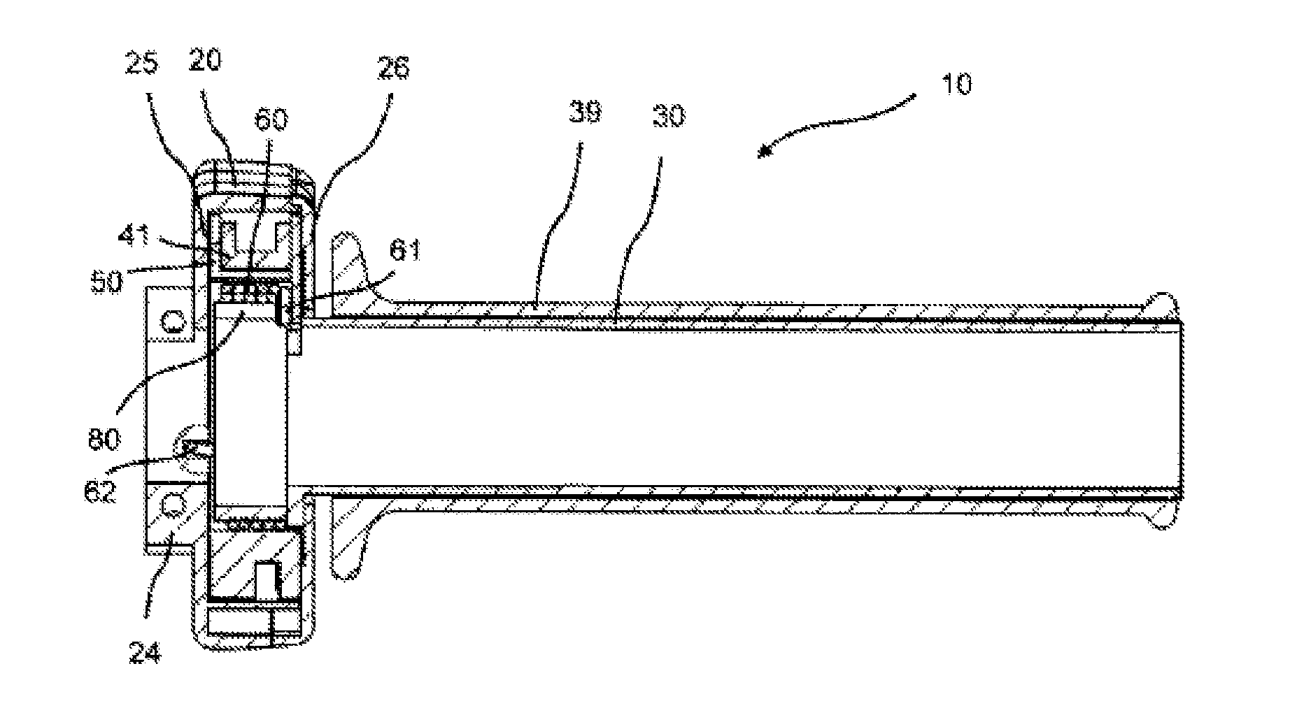
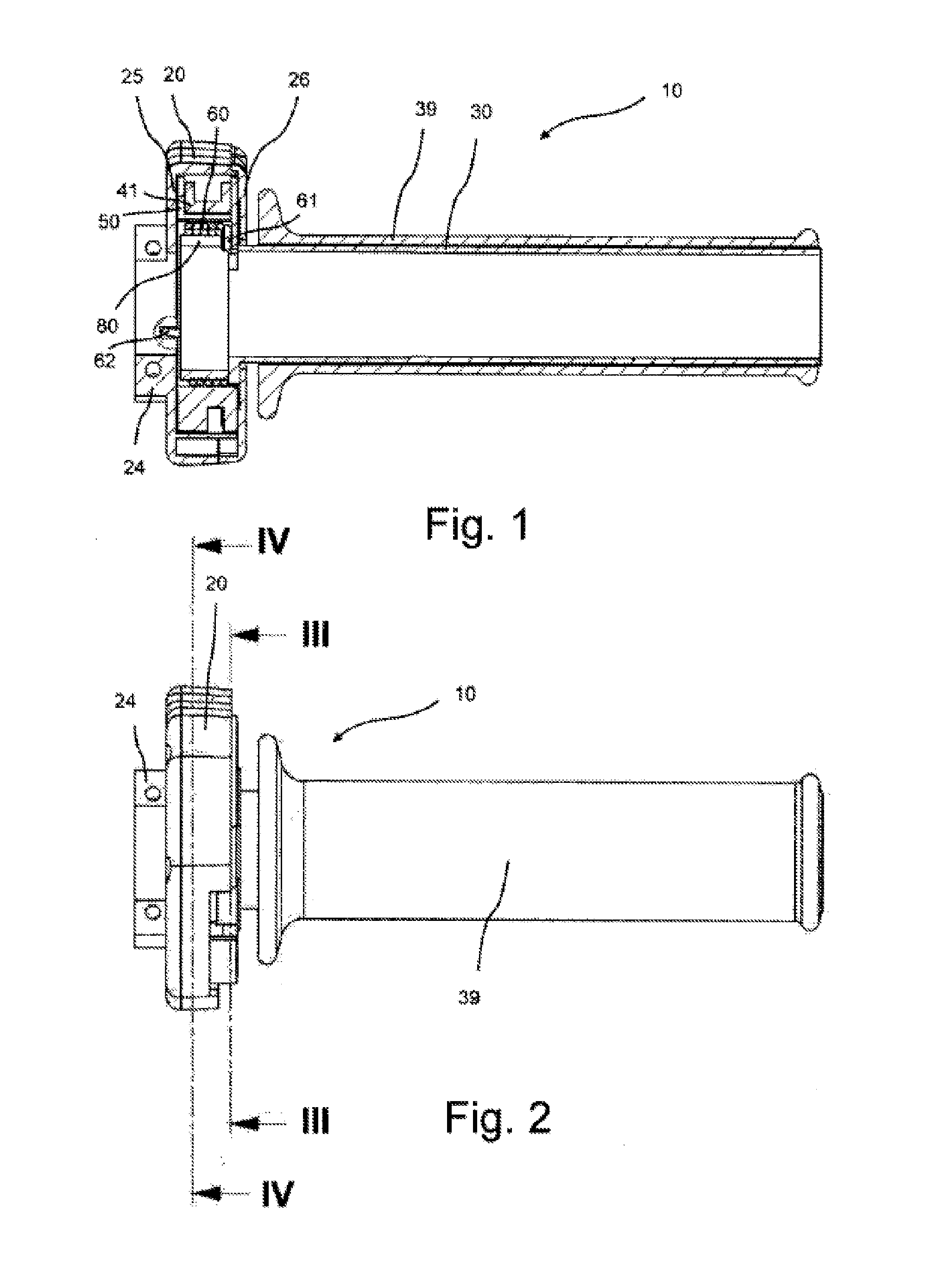
[0092]FIGS. 1 to 4 show a first exemplary embodiment of a throttle twist grip 10 according to the invention.
[0093]The throttle twist grip 10 has a housing 20. The housing 20 is mounted in known manner on a handlebar tube (not shown) by means of a clamping device 24.
[0094]The housing 20 preferably has a two-part design and includes a basic body 25 and a housing cover 26. Alternatively, the housing can also be made of one piece or of several pieces.
[0095]In the housing 20, a grip tube 30 is mounted rotatably which accommodates a hand rest body 39 that is gripped with one hand by the rider of the handlebar-controlled vehicle (e.g. motorbike, trike, quad or bicycle having an auxiliary power means).
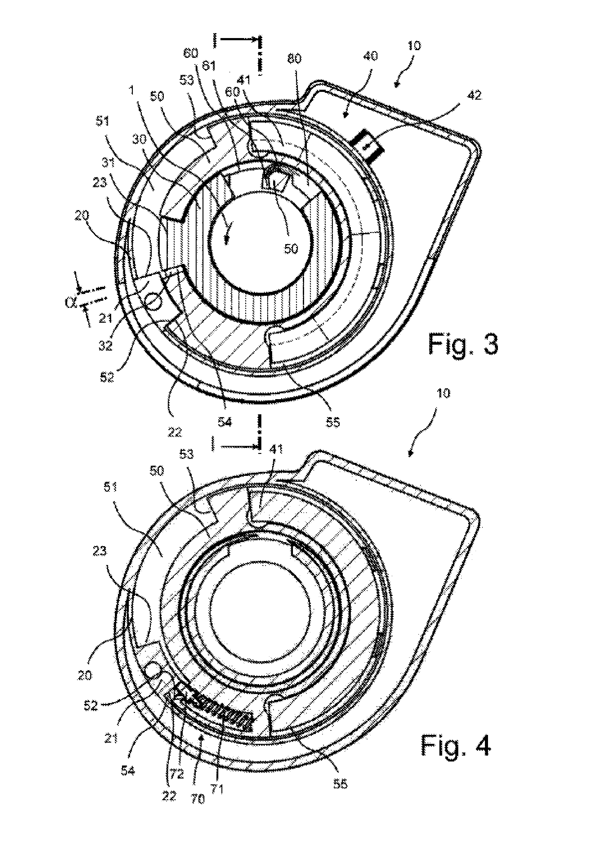
[0096]The housing 20 accommodates a projection 21 where an idling stop 22 and a full-throttle stop 23 are provided. The projection 21 protrudes radially inwards from the housing wall. The idling stop 22 and a full-throttle stop 23 are provided on both sides thereof.
[0097]The throttle twist gri...
PUM
 Abstract
Description
Claims
Application Information