Device for protection of a live element mounted on a support in an electrical box

a technology for protecting devices and live parts, applied in electrical devices, substations/switching arrangements, substations/switching boards/panels/desks, etc., can solve the problems of only partial protection offered by such protection devices, unable to verify the tightness of fixing means, and liable to become detached electrically conductive elements fixed to the box. , to achieve the effect of convenient fitting of protection devices and improved protection

Inactive Publication Date: 2013-05-09
ECE GMBH
View PDF6 Cites 6 Cited by
  • Summary
  • Abstract
  • Description
  • Claims
  • Application Information

AI Technical Summary

Benefits of technology

[0016]The articulated junction thus enables the provision of a cap covering the live element and protecting it from any contact with the surrounding elements and enables access to the live element in order to monitor its state or to perform maintenance operations.
[0017]The cap, the retaining means and the articulated junction may advantageously be made in one piece,

Problems solved by technology

For example, electrically conductive elements fixed to the box are liable to become detached because of vibrations generated in flight, drop to the bottom of the box and come into contact with the distribution bars.
However, such a system has the major drawback that once the varnish has been evaporated maintenance is more difficult given that the parts must be cleaned before reassem

Method used


Image

  • Device for protection of a live element mounted on a support in an electrical box
  • Device for protection of a live element mounted on a support in an electrical box

Examples


Embodiment Construction

[0034]It is to be understood the present invention is not limited to particular devices or methods, which may, of course, vary. It is also to be understood that the terminology used herein is for the purpose of describing particular embodiments only, and is not intended to be limiting. As used in this specification and the appended claims, the singular forms “a”, “an”, and “the” include singular and plural referents unless the content clearly dictates otherwise. Furthermore, the word “may” is used throughout this application in a permissive sense (i.e., having the potential to, being able to), not in a mandatory sense (i.e., must). The term “include,” and derivations thereof, mean “including, but not limited to.” The term “coupled” means directly or indirectly connected.

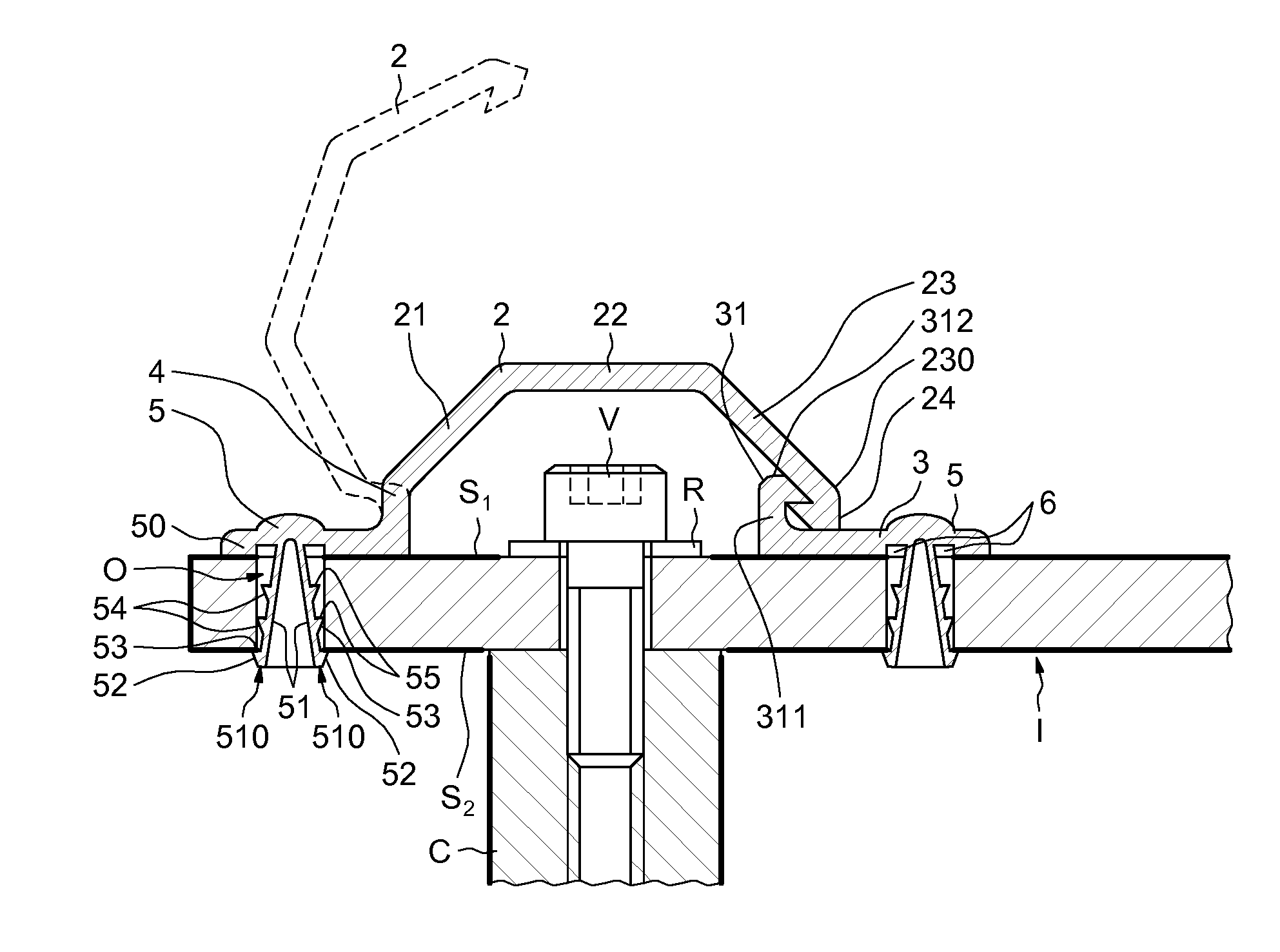
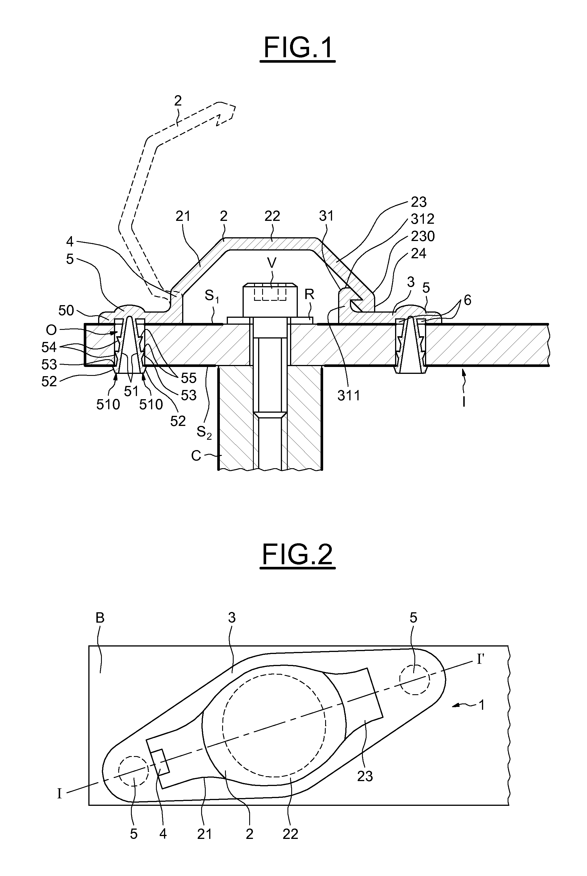
[0035]In FIG. 1 there is represented a view in section taken along the line I-I′ of a device 1 for protecting a screw V fixing an electrical distribution bar B to a connecting terminal C in one embodiment of the inve...


PUM

PropertyMeasurementUnit
Thicknessaaaaaaaaaa
Electrical conductoraaaaaaaaaa
Dimensionaaaaaaaaaa

Abstract

Device for protection of a live element mounted on a support in an electrical distribution box, comprising an insulative cap adapted to cover the live element and retaining means adapted to retain the protection device fixed to the support. The protection device comprises an articulated junction adapted to couple the cap to the retaining means so that the cap is articulated relative to the retaining means in a first position in which the live element is electrically protected and a second position enabling access to the live element.

Description

BACKGROUND OF THE INVENTION[0001]1. Field of the Invention[0002]The invention concerns the protection of live parts in an electrical box, and more particularly the protection of the systems for fixing a distribution bar in an electrical distribution box.[0003]2. Description of the Relevant Art[0004]The distribution of electrical energy, for example in an aircraft, is generally effected with the aid of electrical distribution boxes relaying by means of cables energy produced by electrical generators driven by engines. An electrical distribution box may then route the received electrical energy to loads or other electrical distribution boxes.[0005]Each electrical distribution box includes distribution components some of which have the function of switching the received electrical energy to a distribution bar contained in the same electrical distribution box or in another electrical distribution box.[0006]A distribution bar is a conductive bar to which are coupled, on the one hand, a s...

Claims


Application Information

Patent Timeline
IPC IPC(8): H01B17/38
CPCH02B1/06H02B1/14Y10T29/49002H01B17/38H02G5/04
Inventor GAUTIER, FREDERIC ALAIN
Owner ECE GMBH
Why Eureka
Try Eureka