Rotary electric machine and method for manufacturing a stator coil connecting unit therefor

a technology of stator coil and connecting unit, which is applied in the direction of dynamo-electric components, windings, synchronous motors, etc., can solve the problems of reducing the assembly ease of centralized distribution members, unable to insert into holding grooves, and causing cost increases. cost

Inactive Publication Date: 2013-05-09
MITSUBISHI ELECTRIC CORP
View PDF3 Cites 30 Cited by
  • Summary
  • Abstract
  • Description
  • Claims
  • Application Information

AI Technical Summary

Benefits of technology

[0011]According to the present invention, because the plurality of busbars are held by the electrically insulating holder such that the external electric power supply terminals pass over the omitted portions of the base portions of the busbars that are positioned on the first side in the radial direction of the electrically insulating holder and extend outward on the first side in the radial direction, the plurality of busbars, which are bent such that the external electric power supply terminals and the coil

Problems solved by technology

Because conventional centralized distribution members for motors have configurations in which the terminal portions and the tabs extend outward from each of the approximately annular busbars in radially opposite directions, if the terminal portions and the tabs are both bent in steps before the approximately annular busbars are inserted into the holding grooves of the insulating holder, as the busbars are inserted into the holding grooves of the

Method used


Image

  • Rotary electric machine and method for manufacturing a stator coil connecting unit therefor
  • Rotary electric machine and method for manufacturing a stator coil connecting unit therefor
  • Rotary electric machine and method for manufacturing a stator coil connecting unit therefor

Examples


embodiment 1

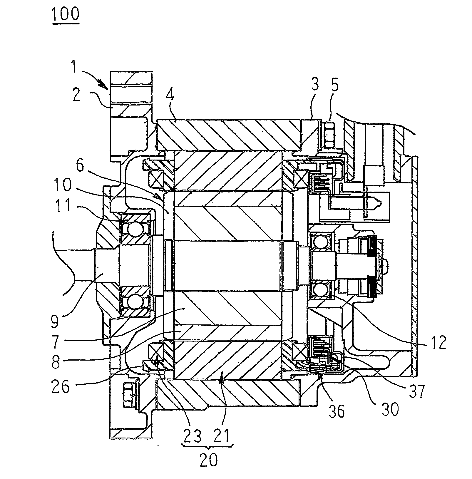
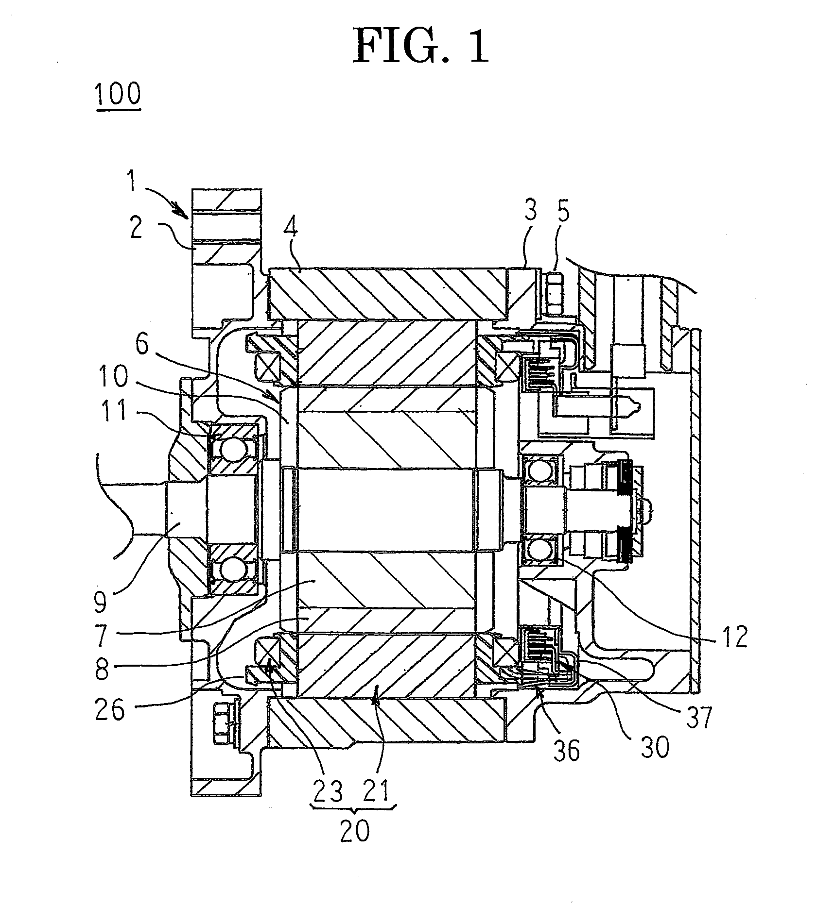
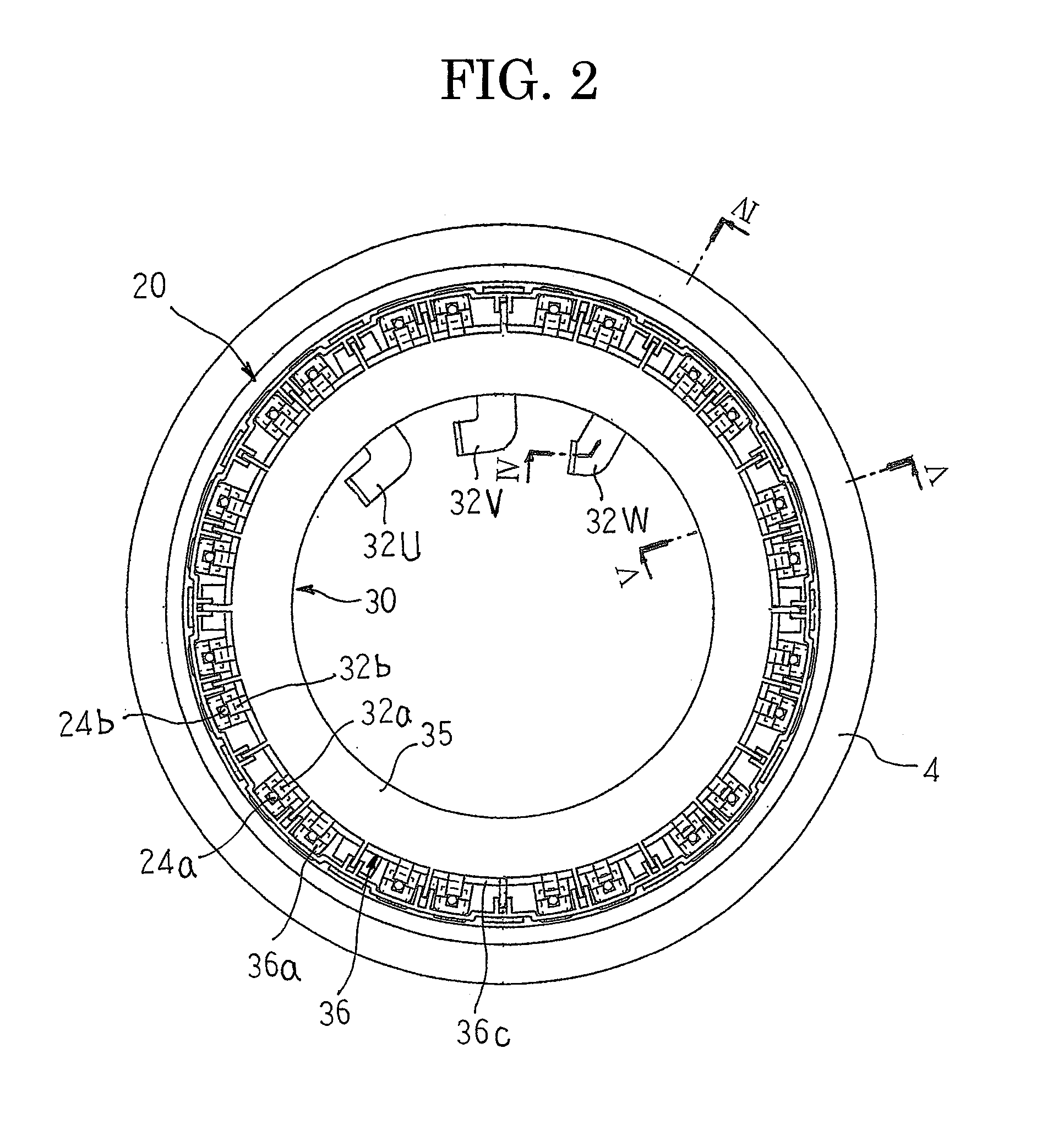
[0032]FIG. 1 is a cross section that shows a rotary electric machine according to Embodiment 1 of the present invention, FIG. 2 is an end elevation that shows a mounted state of a connecting unit of a stator of the rotary electric machine according to Embodiment 1 of the present invention, FIG. 3 is an end elevation that shows the stator of the rotary electric machine according to Embodiment 1 of the present invention, FIG. 4 is a cross section that is taken along Line IV-IV in FIG. 2 so as to be viewed in the direction of the arrows, FIG. 5 is a cross section that is taken along Line V-V in FIG. 2 so as to be viewed in the direction of the arrows, FIGS. 6 and 7 are respective partial cross sections that show a mounted state of a cover of the stator of the rotary electric machine according to Embodiment 1 of the present invention, FIG. 8 is a perspective that shows a core unit of the stator of the rotary electric machine according to Embodiment 1 of the present invention, FIG. 9 is ...

embodiment 2

[0076]FIG. 16 is an end elevation that shows a mounted state of a connecting unit of a stator of a rotary electric machine according to Embodiment 2 of the present invention, FIG. 17 is a cross section that is taken along Line XVII-XVII in FIG. 16 so as to be viewed in the direction of the arrows, FIG. 18 is an end elevation that shows a state of the connecting unit of the stator coil of the rotary electric machine according to Embodiment 2 of the present invention before insert molding, and FIGS. 19A through 19D are end elevations that show busbars that are used in the connecting unit of the stator coil of the rotary electric machine according to Embodiment 2 of the present invention.

[0077]In FIGS. 16 through 18, a connecting unit 40 includes: a plurality of busbars 41N, 41U, 41V, and 41W that perform predetermined connection of concentrated winding coils 24; an electrically insulating holder 33 that houses and holds the plurality of busbars 41N, 41U, 41V, and 41W; and an exterior ...


PUM

PropertyMeasurementUnit
Thicknessaaaaaaaaaa
Widthaaaaaaaaaa

Abstract

Busbars that are disposed so as to correspond to respective phases of a stator coil each include: a base portion that is formed so as to have an incomplete annular shape; external electric power supply terminals that extend radially inward from a first circumferential end of the base portion; and a plurality of coil connecting terminals that each extend radially outward from the base portion, that are arranged in a row so as to have a predetermined spacing in a circumferential direction of the base portion, and that are connected to coil terminals of concentrated winding coils, and the busbars are held by the electrically insulating holder such that the external electric power supply terminals extend radially inward so as to pass over omitted portions of the base portions of the busbars that are positioned radially inside the electrically insulating holder.

Description

BACKGROUND OF THE INVENTION[0001]1. Field of the Invention[0002]The present invention relates to a rotary electric machine that is used in an automotive motor, for example, and to a method for manufacturing a stator coil connecting unit therefor.[0003]2. Description of the Related Art[0004]Conventional centralized distribution members for motors include: a plurality of approximately annular busbars that have: terminal portions that are connected to a battery; and tabs that are connected to windings of a stator, and that are disposed so as to correspond to respective phases of a motor; an electrically insulating holder that has holding grooves that hold the approximately annular busbars, which are disposed so as to be laminated radially on the centralized distribution member, so as to be separated from each other by a predetermined spacing; a resin electrically insulating layer that is formed by insert molding, and that covers the respective busbars and the insulating holder, the ter...

Claims


Application Information

Patent Timeline
IPC IPC(8): H02K19/02H01R43/18H01R43/20
CPCY10T29/49208Y10T29/4922H02K2203/09H02K3/522Y10T29/49012
Inventor IKURA, YUTAKA
Owner MITSUBISHI ELECTRIC CORP
Why Eureka
Try Eureka