Rotating element with embedded permanent magnet and rotating electrical machine

Inactive Publication Date: 2013-05-09
TOYOTA IND CORP
View PDF21 Cites 6 Cited by
  • Summary
  • Abstract
  • Description
  • Claims
  • Application Information

AI Technical Summary

Benefits of technology

[0006]Since the second permanent magnets 98 are located near the outer circumference surface of the rotor core 94, the alternating field interlinking with the second permanent magnets 98 becomes large, and the second permanent magnets 98 produce a large eddy current los

Problems solved by technology

In order to reduce the eddy current loss, for example, adaptation of a magnet with a high coercive force as the second permanent magnet 98, increase of the thickness of the s

Method used


Image

  • Rotating element with embedded permanent magnet and rotating electrical machine
  • Rotating element with embedded permanent magnet and rotating electrical machine
  • Rotating element with embedded permanent magnet and rotating electrical machine

Examples


first embodiment

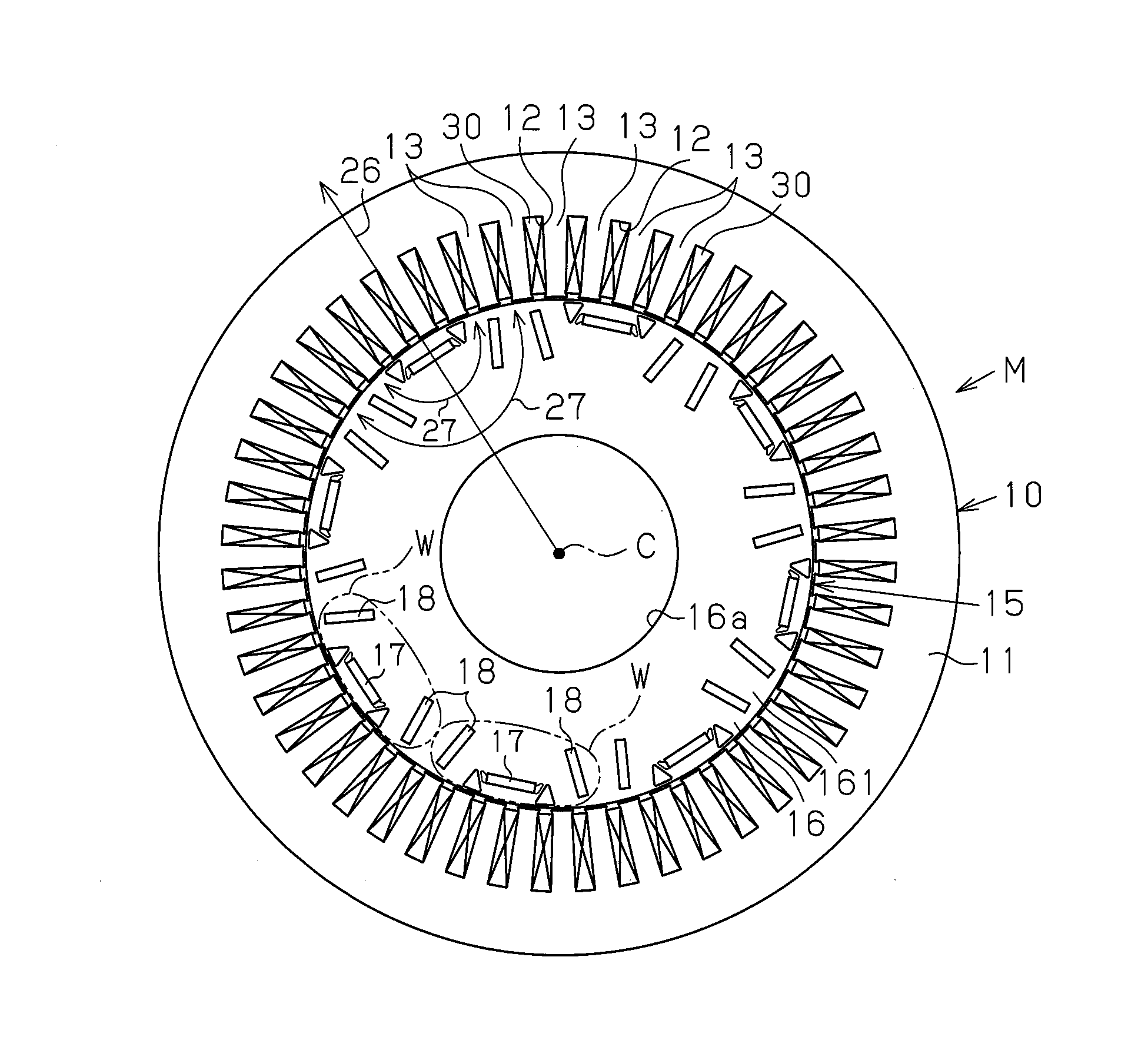
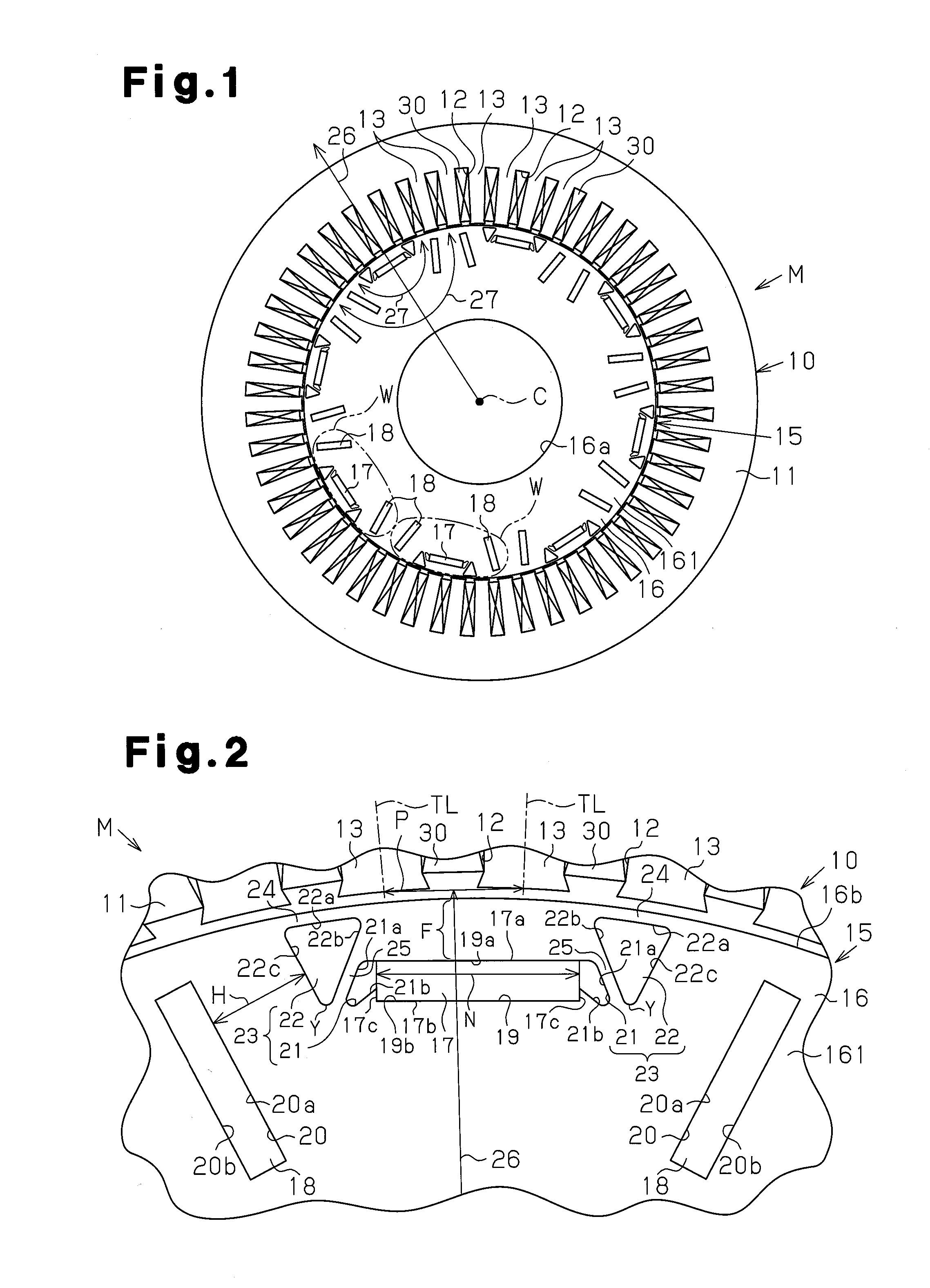
[0018]A first embodiment according to the present invention will now be described with reference to FIGS. 1 and 2.

[0019]As illustrated in FIG. 1, a permanent-magnet-embedded rotating electrical machine M includes an annular stator 10 and a permanent-magnet-embedded rotor 15 (hereinafter, simply referred to as a rotor 15) provided inwardly of the stator 10 in a rotational manner. The stator 10 includes an annular stator core 11. The stator core 11 is formed by laminating a plurality of core plates formed of a magnetic material (steel sheet).

[0020]A plurality of teeth 13 are arranged around the inner circumference of the stator core 11. A slot 12 is formed between adjoining teeth 13 in the circumferential direction of the stator core 11. A coil 30 is built in each slot 12. As illustrated in FIG. 2, it is assumed that a length of a tooth 13 in a direction orthogonal to the radial direction of the stator core 11 is a width of the tooth 13. It is also assumed that a straight line extendi...

second embodiment

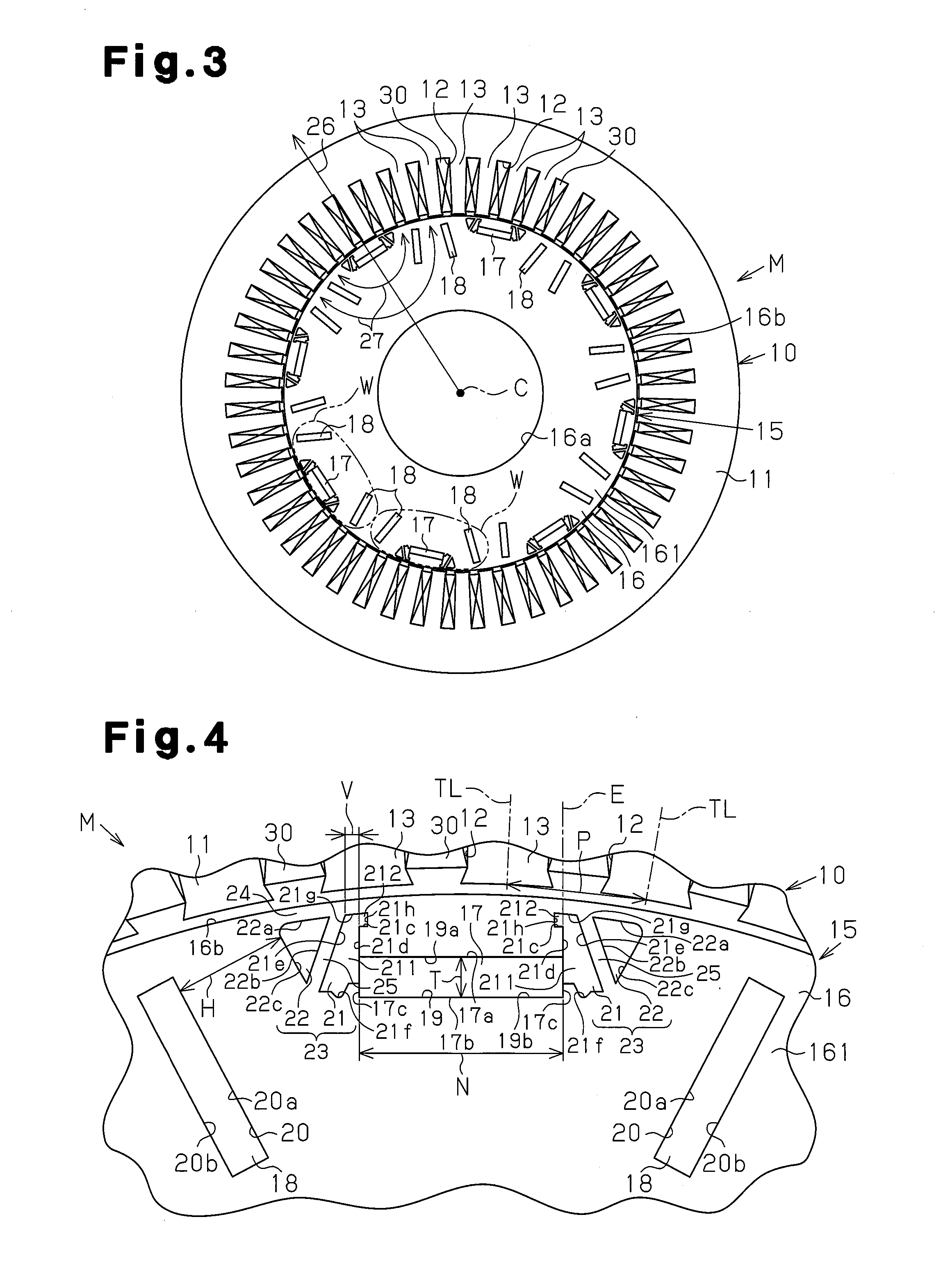
[0077] the pair of reinforcement bridges 25 is arranged in a reversed V shape to spread the pitch therebetween from the side corresponding to the outer-circumferential-surface-16b of the rotor core 16 toward the inner side thereof in the radial direction. Instead of such a structure, the pair of reinforcement bridges 25 may be arranged in a V shape to reduce the pitch therebetween from the side corresponding to the outer-circumferential-surface-16b of the rotor core 16 toward the inner side thereof in the radial direction. Moreover, the pair of reinforcement bridges 25 may be arranged to have a constant clearance therebetween.

[0078]In the second embodiment, the outer-circumferential-side bridge 24 and the reinforcement bridge 25 may have respective widths equal to or smaller than twice the thickness of the core plate 161.

[0079]According to the second embodiment, the extended part 212 of the first gap 21 may be formed to gradually become thin toward the d-axis 26 from the base 211. I...


PUM


Abstract

A rotating element with embedded permanent magnets is provided that includes: a rotor core adapted to be within the diameter direction of a stator; first permanent magnets embedded near the exterior circumference face of the core, and orthogonally extending with a d axis; and second permanent magnets embedded on both sides of each of the first magnets, and extending along a q axis. The rotating element further includes gaps formed in the core away from both circumference direction ends of the first magnets. The gaps further include exterior end parts at the furthermost exterior side with respect to the diameter direction of the core, and interior end parts at the furthermost interior side with respect to same. The magnetic pole faces of the first magnets are located between the exterior and interior end parts of the gaps.

Description

FIELD OF THE INVENTION[0001]The present invention relates to a permanent-magnet-embedded rotor that includes a first permanent magnet embedded near an outer circumference surface of a rotor core and extending in a direction orthogonal to a d-axis, a second permanent magnet embedded in the rotor core and extending along a q-axis, and a gap formed in the rotor core to be distant from the first permanent magnet toward the second permanent magnet. The present invention also relates to a rotating electrical machine having the rotor.BACKGROUND ART[0002]As illustrated in FIG. 7, a permanent-magnet reluctance rotating electrical machine 90 disclosed in Patent Document 1 includes a stator 92 having a plurality of armature coils 91, and a rotor 93 arranged inwardly of the stator 92 in the radial direction.[0003]The rotor 93 includes a cylindrical rotor core 94. The rotor core 94 is provided with a plurality of magnetic poles. A plurality of pairs of first hollows 95 in a rectangular shape are...

Claims


Application Information

Patent Timeline
IPC IPC(8): H02K1/27
CPCH02K1/2706H02K1/2766
Inventor SAITO, YOICHIYOSHIDA, TOSHIHIKOHATTORI, TATSUYA
Owner TOYOTA IND CORP
Why Eureka
Try Eureka