Controller for motor

a controller and motor technology, applied in the direction of motor/generator/converter stopper, dynamo-electric converter control, motor/generator/converter stopper, etc., can solve the problem of inability to change the controllable range of output torque between driving mode and power generating mode, inconveniently preventing flexible changes of output torque control range, and insufficient control amount of weakening field. problem, to achieve the effect of reducing field weaken

Inactive Publication Date: 2007-09-27
HONDA MOTOR CO LTD
View PDF2 Cites 9 Cited by
  • Summary
  • Abstract
  • Description
  • Claims
  • Application Information

AI Technical Summary

Benefits of technology

[0024]With this arrangement, an inductance Ld of the armature disposed on the d-axis changes as the rotor phase difference changes, so that the accuracy of the estimation of the rotor phase difference can be further improved by estimating the rotor phase difference by using the inductance of the armature disposed on the d-axis in addition to the inductance of the armature disposed on the q-axis and the induced voltage constant of the motor.
[0025]The controller for a motor further includes a field weakening current corrector for controlling the amount of energization of the armature disposed on the d-axis so as to reduce a field weakening shortage due to a change in the rotor phase difference on the basis of a difference between a command value of the rotor phase difference when the field of the motor is weakened by the field control and an estimated value of the rotor phase difference obtained by the phase difference estimator.
[0026]With this arrangement, if a difference occurs between a command value of the rotor phase difference when weakening the field of the motor by the field control and an estimated value due to a response delay or the like of the rotor phase difference changer, then the amount of energization of the armature on the d-axis is controlled to reduce the field weakening shortage due to a change in the rotor phase difference by the field weakening current corrector. This makes it possible to restrain a shortfall of field weakening from occurring due to an influence of a response delay or the like of the rotor phase difference changer.

Problems solved by technology

Hence, the conventional field weakening control, which depends merely on the number of revolutions, inconveniently results in an excessive or insufficient control amount for weakening the field.
This inconveniently prevents flexible changes of the controllable range of output torque or the number of revolutions of the motor.
However, when changing the phase difference between the first rotor and the second rotor by the number of revolutions or a centrifugal force, it is disadvantageous that the field control amount cannot be changed between the driving mode and the power generating mode.
Furthermore, the controller of the motor does not detect an actual phase difference between the first rotor and the second rotor, so that an expected field weakening effect may not be obtained.

Method used


Image

  • Controller for motor
  • Controller for motor
  • Controller for motor

Examples


Embodiment Construction

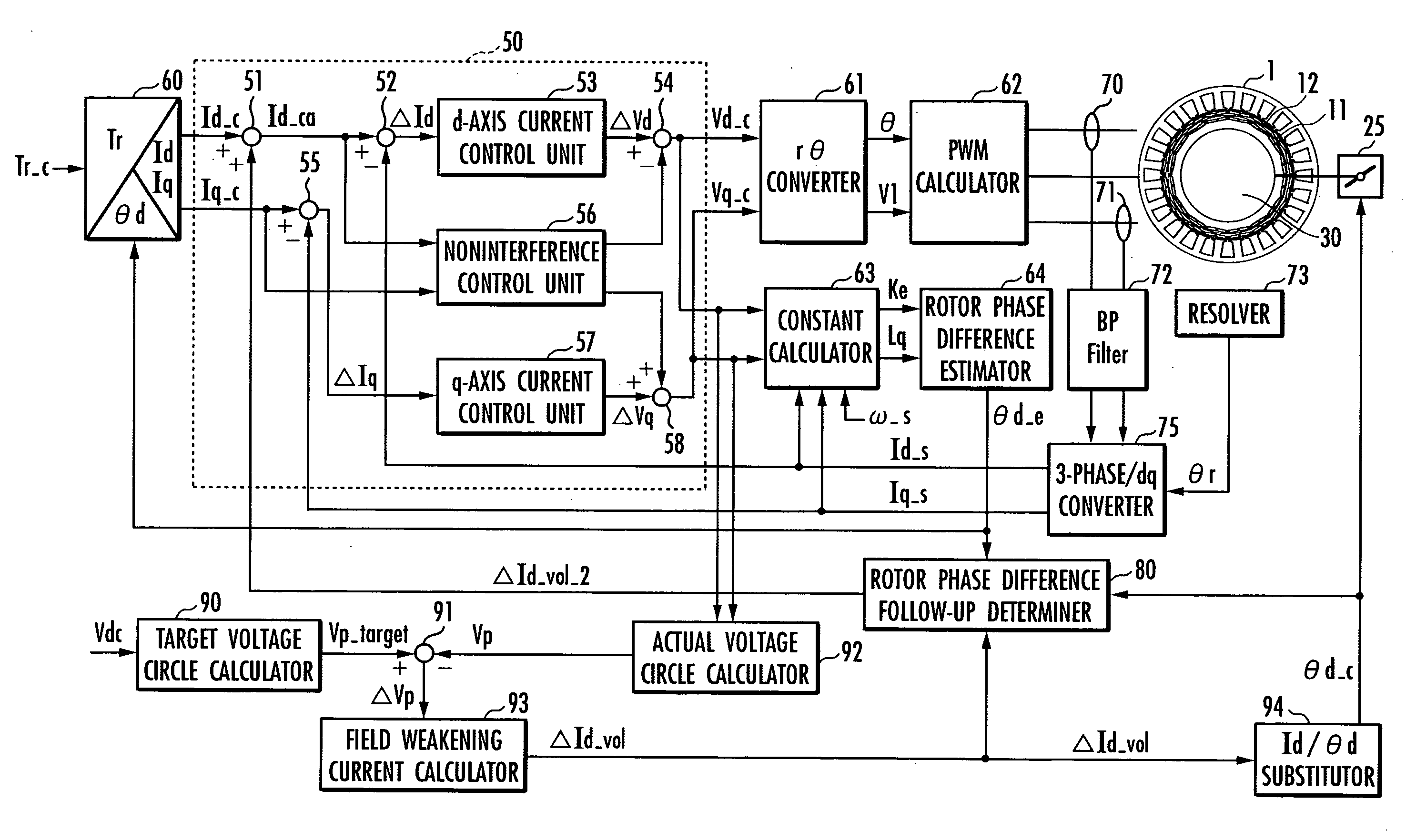
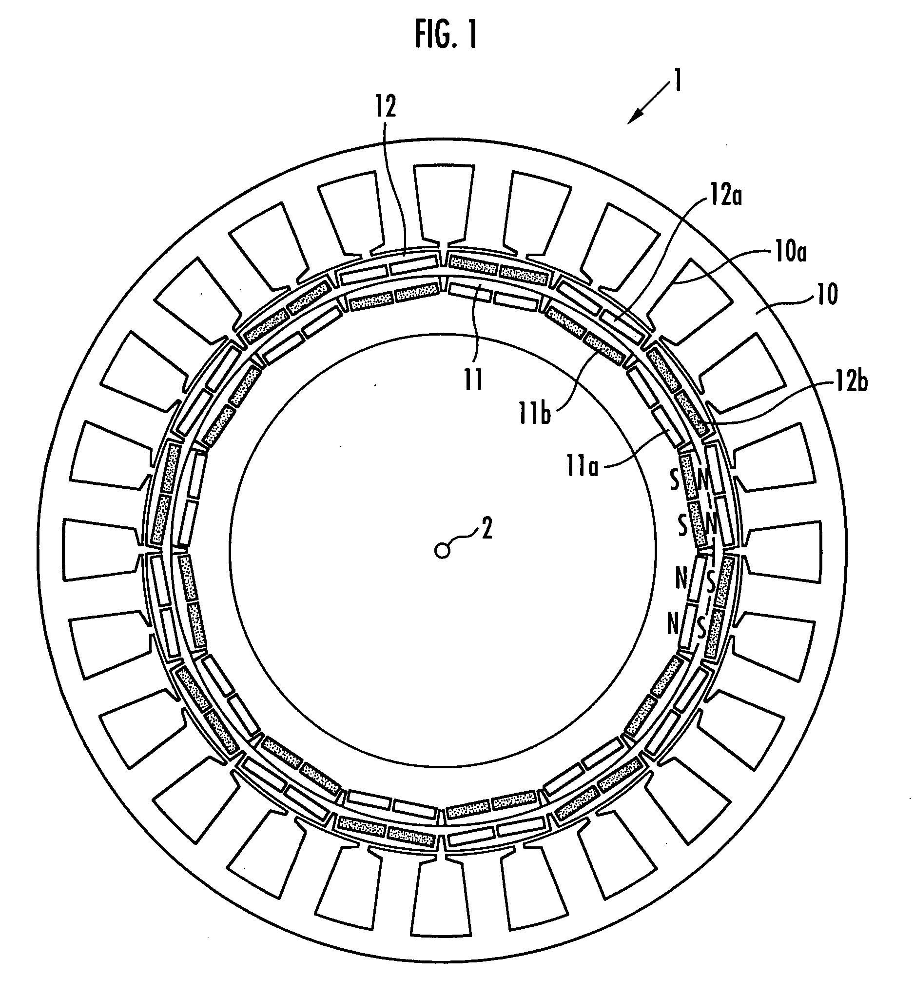
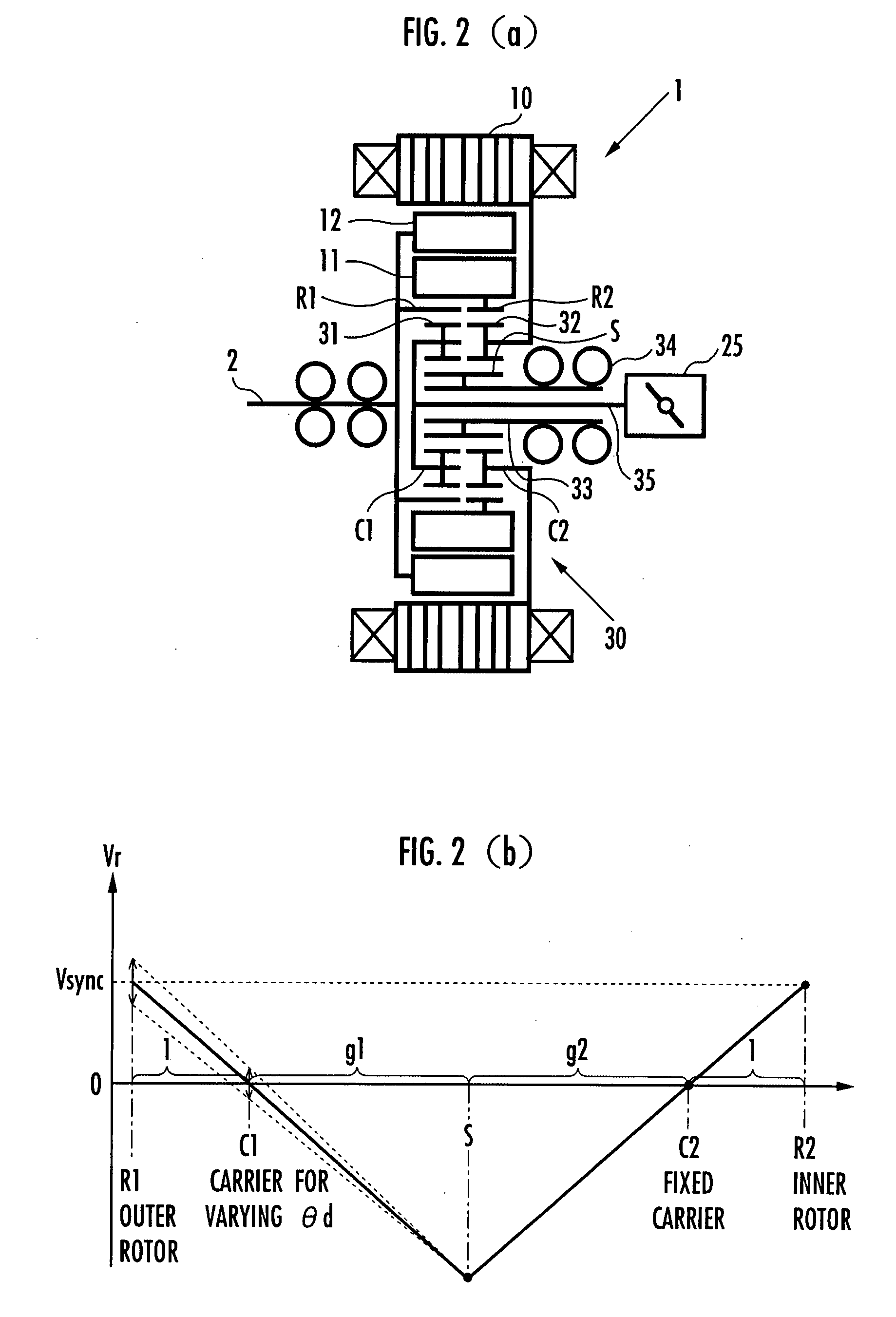
[0039]An embodiment of the present invention will be explained with reference to FIG. 1 to FIG. 11. FIG. 1 is a configuration diagram of a DC brushless motor provided with a double rotor, FIG. 2 is a configuration diagram and an operation explanatory diagram of a mechanism for changing a phase difference between an outer rotor and an inner rotor of a DC brushless motor shown in FIG. 1, FIG. 3 and FIG. 4 are explanatory diagrams of an advantage provided by changing the phase difference between the outer rotor and the inner rotor, FIG. 5 is a control block diagram of a controller of a motor, FIG. 6 is a voltage vector diagram in a dq coordinate system, FIG. 7 is an explanatory diagram of a data table for determining an induced voltage constant, FIG. 8 is a flowchart of processing for changing the phase difference between the outer rotor and the inner rotor, FIG. 9 is a flowchart of processing for compensating for a follow-up delay of an estimated value relative to a command value of t...


PUM


Abstract

A controller for a motor performs field weakening control by changing a phase difference between two rotors, which are concentrically disposed, and by accurately recognizing the phase difference. The controller for a motor includes an actuator and a planetary gear mechanism that change a rotor phase difference on the basis of a command value of a phase difference (rotor phase difference) between an outer rotor and an inner rotor of a motor in field weakening control, a constant calculator which calculates an induced voltage constant of the motor and an inductance of a q-axis armature on the basis of a d-axis current detection value, a q-axis current detection value, d-axis voltage command value, a q-axis voltage command value, and an angular velocity of the motor, a rotor phase difference estimator which determines an estimated value of the rotor phase difference on the basis of the induced voltage constant and the q-axis inductance, and a current command value determiner which determines a command value of d-axis current and a command value of q-axis current by using the estimated value.

Description

BACKGROUND OF THE INVENTION[0001]1. Field of the Invention[0002]The present invention relates to a controller for a motor adapted to carry out field weakening control of a permanent magnet field type rotary motor by changing a phase difference between two rotors, which are concentrically disposed.[0003]2. Description of the Related Art[0004]Hitherto, there has been known a motor which is constituted of a permanent magnet field type rotary motor equipped with a first rotor and a second rotor concentrically provided around a rotating shaft and which is adapted to conduct field weakening control by changing the phase difference between the first rotor and the second rotor according to a rotational velocity (refer to, for example, Japanese Patent Application Publication No. 2002-204541).[0005]In such a conventional motor, the first rotor and the second rotor are connected through the intermediary of a member that displaces in the radial direction when subjected to a centrifugal force. T...

Claims


Application Information

Patent Timeline
Patent Type & Authority Applications(United States)
IPC IPC(8): H02P1/00H02K1/27H02K16/02H02P6/06H02P6/08H02P6/15H02P6/16H02P6/28H02P21/00H02P21/06H02P21/22H02P27/04H02P27/08
CPCH02P21/0089H02P2207/05H02P2207/03H02P21/06
Inventor ATARASHI, HIROFUMI
Owner HONDA MOTOR CO LTD
Why Eureka
Try Eureka