I.v. infusion or blood collection apparatus

a technology of blood collection and infusion device, which is applied in the field of medical devices, can solve the problems of affecting the health and safety of health care workers around the world, the risk of potentially fatal disease transmission, and other sharp medical devices, and achieves the effect of improving safety features

Active Publication Date: 2013-05-09
MDDP
View PDF2 Cites 18 Cited by
  • Summary
  • Abstract
  • Description
  • Claims
  • Application Information

AI Technical Summary

Benefits of technology

[0010]It is thus an object of the invention to provide an improved I.V. infusion or blood collection apparatus.
[0011]It is a further object of the present invention to provide an improved I.V. infusion or blood collection apparatus having enhanced safety features.
[0010]It is thus an object of the invention to provide an improved I.V. infusion or blood collection apparatus.

Problems solved by technology

Notwithstanding the foregoing, injuries caused by needles and other sharp medical devices and the related risk of potentially fatal disease transmission remain a major threat to the health and safety of health care workers around the world.
In addition, the distress, sickness and absenteeism resulting from sharps injuries constitute a considerable strain on the already limited human resources in the medical profession.
Ancillary staff such as cleaners and laundry staff and other downstream workers, are also at risk.
There are several scenarios that describe the accidental needle stick injury: First, a handler may be stuck by a syringe needle while attempting to re-cap the needle after it has been used.
Second, a handler may be stuck by a syringe needle while transporting it to a proper “Sharps Container.” Third, a handler or other individuals may be stuck when contacting a syringe and needle that has been left unprotected and unattended.
Fourth, individuals that transport medical waste may be stuck by unprotected, uncapped or improperly stored syringes and needles.

Method used


Image

  • I.v. infusion or blood collection apparatus
  • I.v. infusion or blood collection apparatus
  • I.v. infusion or blood collection apparatus

Examples


Embodiment Construction

[0044]While the present invention will be described more fully hereinafter, it is to be understood at the outset that persons of skill in the art may modify the present invention herein described while still achieving the favorable results of the invention. Accordingly the description which follows is to be understood as a broad teaching disclosure directed to persons of skill in the appropriate arts, and not as limiting upon the present invention.

[0045]For ease of reading, in the description that follows the I.V. infusion or blood collection apparatus will at times be referred to as the “BCS”, blood collection set.

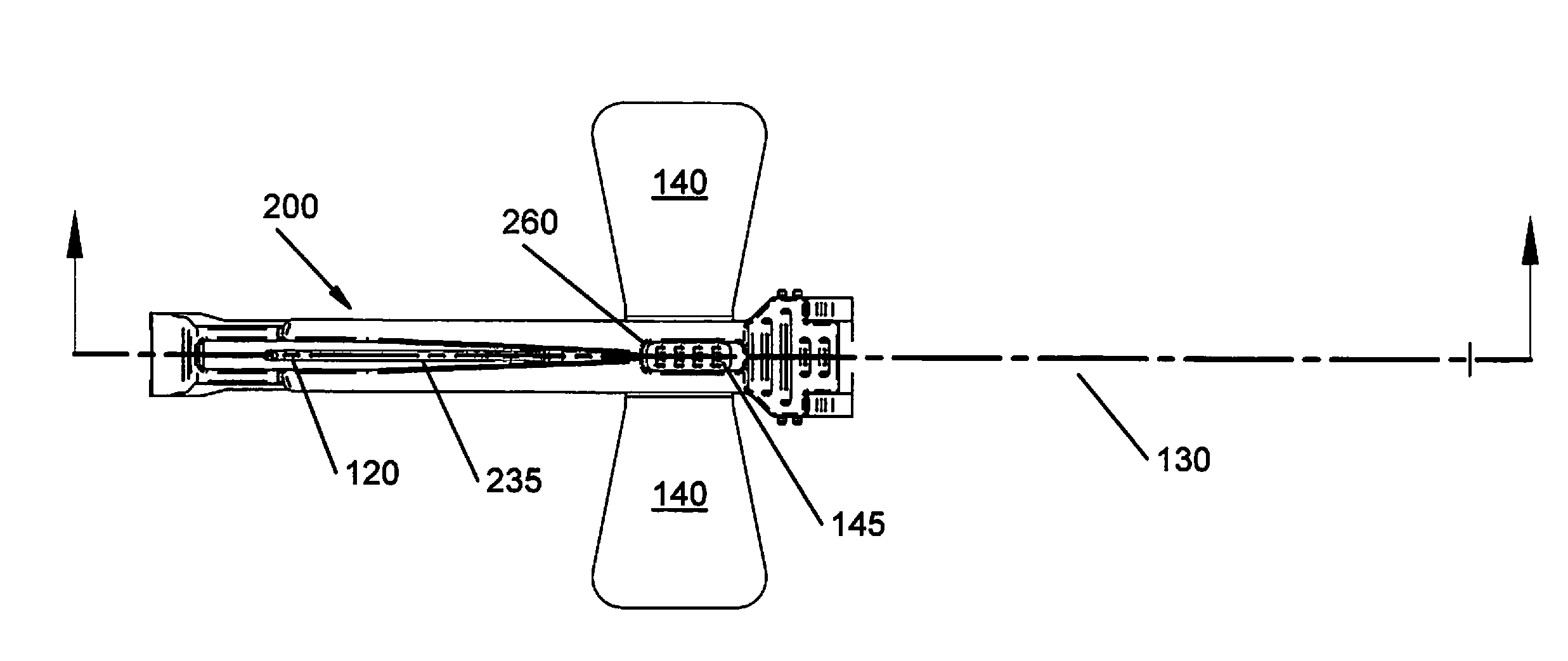
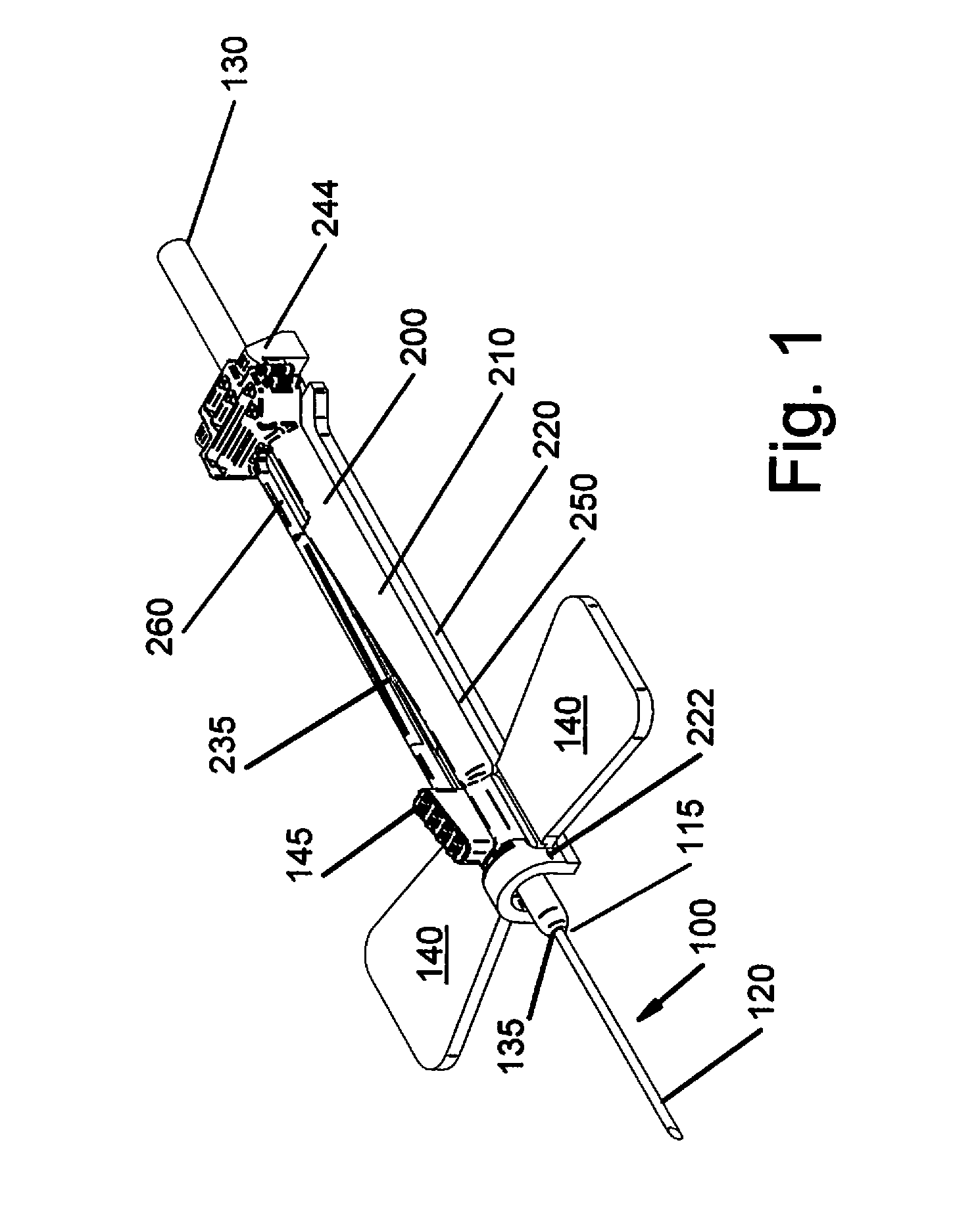
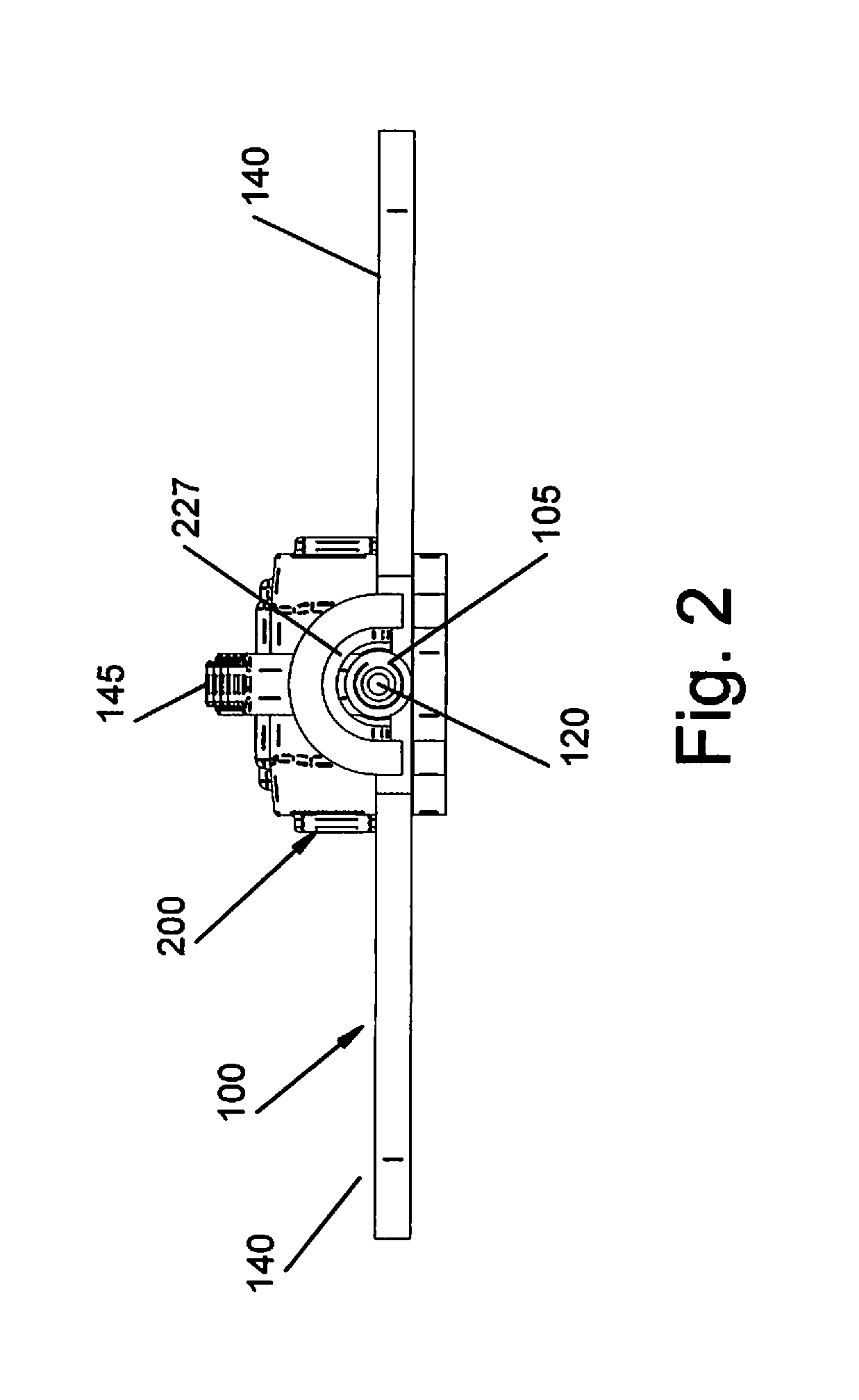
[0046]As shown in the figures, the BCS 50 according to the present invention comprises an I.V. infusion set 100 and a safety shield 200.

[0047]I.V. infusion set 100 comprises a wing body 105 having a central portion 110 with a proximal end 115 to which a needle 120 is connected and a distal end 125 to which tubing 130 is connected. A longitudinal bore 135 extends through t...


PUM


Abstract

An I.V. infusion or blood collection apparatus comprises an I.V. infusion set (100) and a safety shield (200). The I.V. infusion set has a wing body (105) from which a pair of wings (140) extend outward there from and a grip (145) extending upward there from. One end of the wing body mounts a needle (120) or catheter and medical tubing (130) is connected to the opposite end. The wing body includes a bore so that fluid flows between the needle and the medical tubing. A safety shield has a top, a bottom and opposing side walls and defines a cavity (227) that is adapted to receive the I.V. infusion set. The safety shield has slots (250) in each of the side walls and a slot (255) in the top. The respective wings and grip are adapted to be positioned in the slots and to slidably move therein. The slot in the top includes a lock that is adapted to receive the grip so that when the needle is retracted into the cavity; the grip is permanently captured therein, thus locking the needle in the fully retracted safety position.

Description

PRIORITY CLAIM[0001]This application claims priority from U.S. Provisional Patent Application Ser. No. 61 / 399,629 filed Jul. 15, 2010, which is incorporated by reference herein in its entirety.FIELD OF THE INVENTION[0002]This invention relates generally to the field of medical devices and more particularly to the field of safety products used for blood collection or infusion to prevent accidental needle sticks.BACKGROUND OF THE INVENTION[0003]The collection of blood from a patient or infusion into a patient are two of the most commonly performed medical procedures in the world. Blood collection is necessary in order to evaluate the chemical constituency of the bodily functions in order to diagnose medical conditions and to validate treatment plans and infusion is necessary to deliver pharmaceuticals, ringers or other preparations in liquid form. Notwithstanding the foregoing, injuries caused by needles and other sharp medical devices and the related risk of potentially fatal disease...

Claims


Application Information

Patent Timeline
Patent Type & Authority Applications(United States)
IPC IPC(8): A61B5/15A61M5/32
CPCA61B5/1405A61M5/3221A61B5/150259A61B5/150389A61B5/150519A61B5/150641A61B5/15074A61B5/150916A61B5/153A61M5/158A61M5/3271A61M25/0606A61M25/0631A61M25/0637A61M2005/1586A61M2005/3247A61B5/15003
Inventor HOWELL, JULIE C.TAYLOR, MICHAEL A.HIGDON, JOHN F.ROSENTHAL, ROBERT G.KUMAR, SANJIV
Owner MDDP
Why Eureka
Try Eureka