Thermal energy storage system

a technology of energy storage and thermal energy, which is applied in the direction of steam accumulators, machines/engines, steam engine plants, etc., can solve the problems of large-scale energy storage systems that are often mismatched, and tend to be cost prohibitive, so as to facilitate sub-atmospheric flashing and facilitate the storage and retrieval of electrical energy

Inactive Publication Date: 2013-05-16
TERRAJOULE
View PDF8 Cites 32 Cited by
  • Summary
  • Abstract
  • Description
  • Claims
  • Application Information

AI Technical Summary

Benefits of technology

[0009]In order to facilitate the storage and retrieval of electrical energy, an electric motor / generator unit may be mechanically coupled to the heat engine / heat pump unit. The electric motor / generator is arranged to drive the heat engine / heat pump unit during the compression of working fluid and to generate electricity during the expansion of the working fluid. The electric motor / generator may be implemented as a single reversible unit or as separate motor and generator devices.
[0010]The hot and cold reservoirs may take the form of pressure vessels or unpressurized reservoirs. When an unpressurized reservoir is used, a sub-atmospheric pressure chamber may be provided to facilitate sub-atmospheric flashing of working fluid to vapor (e.g., liquid water to steam) and / or sub-atmospheric condensation of vapor to a liquid. When a pressurized vessel is used as the hot reservoir, the working fluid in the hot reservoir may be stored at a pressure substantially above ambient atmospheric pressure.
[0011]In some alternative embodiments, the cold store may be replaced by the combination of a condenser arranged to condense steam and a separate low temperature thermal energy source arranged to provide steam having a lower temperature than the hot reservoir.

Problems solved by technology

By way of example, the availability of some alternative energy sources such as solar energy and wind energy can vary significantly over the course of a day and the output of devices that harvest such energy, (e.g., photovoltaic collectors or wind turbines) is often mismatched with the demand for the electrical energy that such devices produce.
Although batteries tend to work well for relatively small-scale energy storage applications, they tend to be cost prohibitive in larger scale energy storage systems.

Method used


Image

  • Thermal energy storage system
  • Thermal energy storage system
  • Thermal energy storage system

Examples


Embodiment Construction

[0020]A number of thermal energy based energy storage and retrieval systems are described. In general, the described storage systems utilize a working fluid having a substantial heat capacity and make use of a phase change to help improve the storage capacity of the system (e.g. a liquid water / steam phase change).

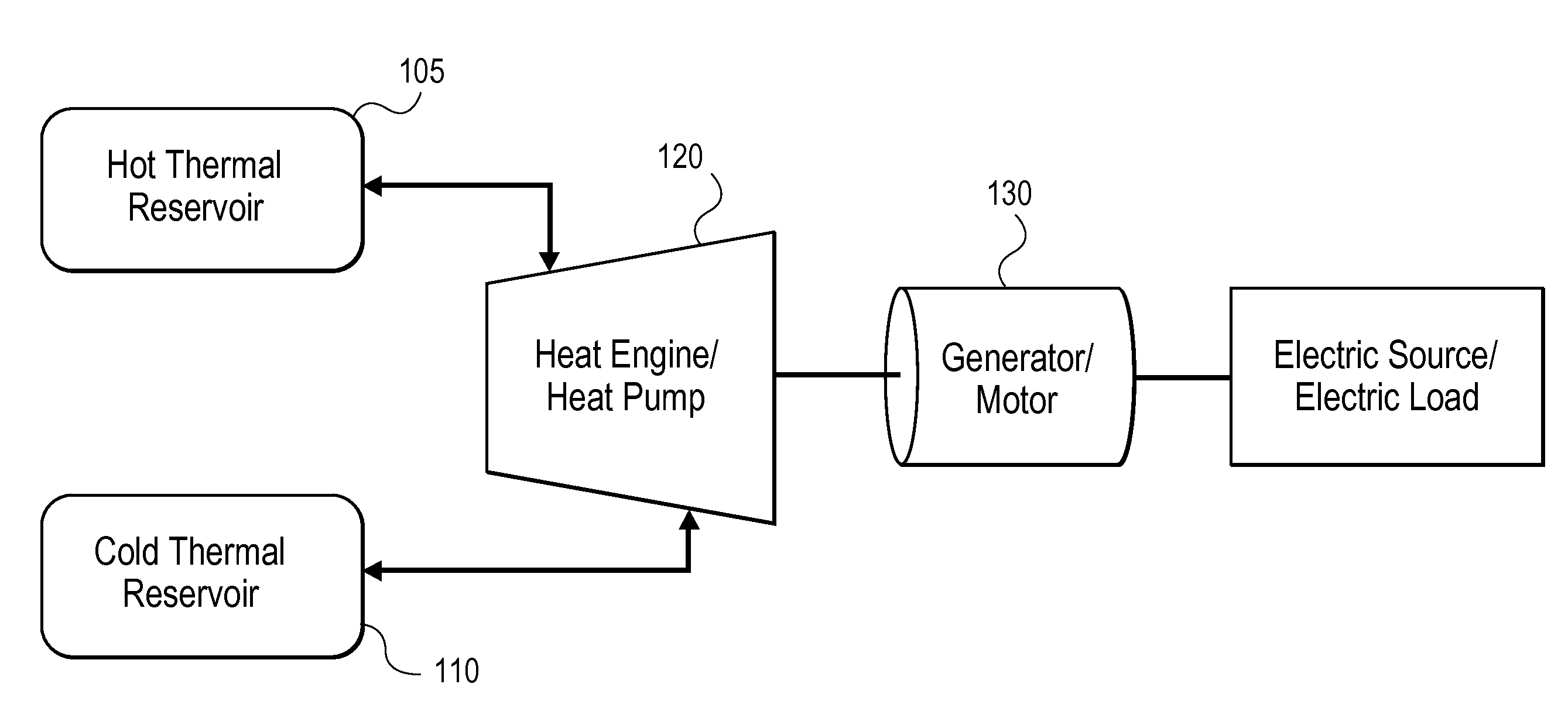
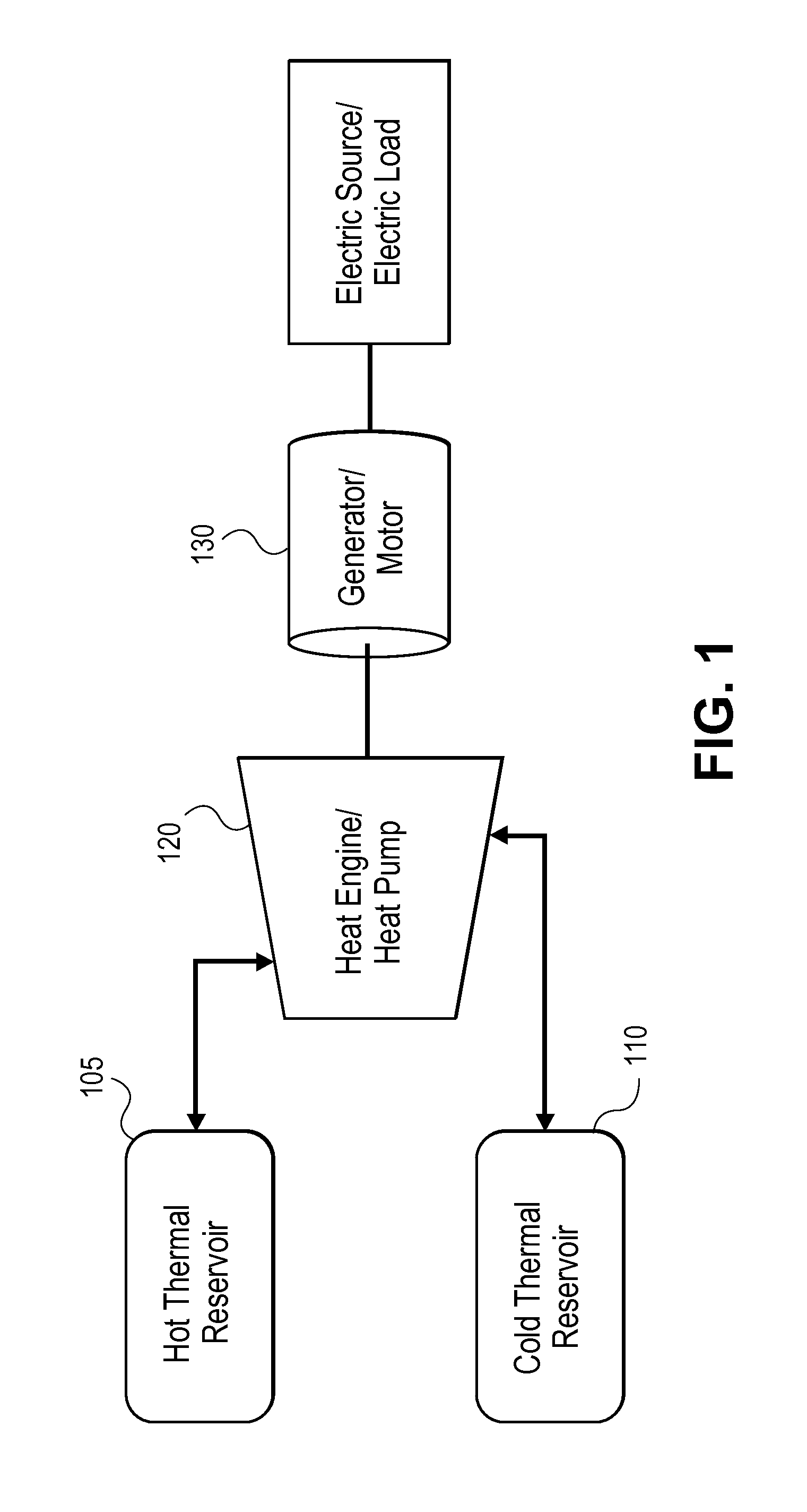
[0021]Referring next to FIG. 1, a basic architecture of a heat engine / heat pump based electrical energy storage and retrieval in accordance with one embodiment of the invention will be described. The storage system 100 includes a “hot” thermal reservoir 105 and a “cold” thermal reservoir 110. A heat engine / heat pump 120 is used to convey a working fluid between the two thermal reservoirs 105 and 110. In the illustrated embodiment, the heat engine / heat pump 120 is coupled to a generator / motor 130 which in turn is coupled to an electric source and the electric load as appropriate. When operating the system 100 in a manner that stores energy, electricity from an electrical sou...


PUM


Abstract

A variety of energy storage and retrieval systems are described. Generally “hot” and “cold thermal reservoirs are provided. The “hot” reservoir holds both liquid and saturated vapor phase working fluid. The “cold” reservoir holds working fluid at a lower temperature than the hot reservoir. A heat engine/heat pump unit: (a) extracts energy from vapor passing from the hot reservoir to the cold reservoir via expansion of the vapor in a manner that generates mechanical energy to facilitate retrieval of energy; and (b) compresses vapor passing from the cold reservoir to the hot reservoir to facilitate the storage of energy. In some embodiments, the heat engine/heat pump takes the form of a reversible positive displacement heat engine that can act as both an expander and a compressor. To facilitate the storage and retrieval of electrical energy, an electric motor/generator unit may be mechanically coupled to the heat engine/heat pump unit.

Description

CROSS REFERENCE TO RELATED APPLICATIONS[0001]This application claims priority to U.S. Provisional Patent Application No. 61 / 559,318, filed Nov. 14, 2011, which is hereby incorporated by reference in its entirety for all purposes.BACKGROUND[0002]The present invention relates generally to thermal energy storage systems. More particularly, it relates to systems that store thermal energy making use of a phase change such as liquid water / steam.[0003]There are many circumstances in which it is desirable to store electrical energy in order to resolve temporal mismatches between energy supply and demand. By way of example, the availability of some alternative energy sources such as solar energy and wind energy can vary significantly over the course of a day and the output of devices that harvest such energy, (e.g., photovoltaic collectors or wind turbines) is often mismatched with the demand for the electrical energy that such devices produce. Another example of the mismatch between supply ...

Claims


Application Information

Patent Timeline
Patent Type & Authority Applications(United States)
IPC IPC(8): F01K3/12
CPCF01K3/12F01K3/006
Inventor MIERISCH, ROBERT CHARLESBISSET, STEPHEN JAMES
Owner TERRAJOULE
Why Eureka
Try Eureka