Elevator installation

a technology for installing elevators and elevators, which is applied in the direction of elevators, transportation and packaging, building lifts, etc., can solve the problems of limiting the transportation capacity of elevator installation and the safety distance required to do so, and achieve the effect of reducing the impact speed, reducing the impact distance, and increasing the impact speed

Inactive Publication Date: 2013-05-16
THYSSENKRUPP ELEVATOR AG (DE)
View PDF11 Cites 14 Cited by
  • Summary
  • Abstract
  • Description
  • Claims
  • Application Information

AI Technical Summary

Benefits of technology

[0008]In the elevator installation in accordance with the invention, in which at least two cars arranged one above the other and movable separately from each other are used, there is arranged on at least one car a stop element which can assume a stop position in which it protrudes laterally from the vertical projection of the first car. The stop element interacts, in order to limit the travel path of this car, with a certain retaining element which is arranged in the shaft outside of the vertical projection of all of the cars. If the car approaches the associated retaining element at low speed, i.e., at a speed that is less than the prescribed limit speed, the brake device arranged on the car or its braking action can be deactivated and, in the event of a malfunction, the travel path can be limited by the stop element and the associated retaining element. For this purpose, the stop and retaining elements are configured such that they can brake the car to a standstill by the stop element impacting the associated retaining element. To this end, the stop element protrudes laterally from the vertical projection of the car so that it can contact the associated retaining element. The associated retaining element limits only the travel path of this one car, whereas the other cars are not impeded in their travel by this retaining element. The function of the brake device arranged on the car can, therefore, be assumed at low speeds, i.e., at speeds less than the limit speed, by the stop element and the associated retaining element. If a second car is located in the region of the retaining element associated with a first car, then the first car can come very close to the second car at low speed. It is possible to go below the safety distance, which is decisive in triggering the brake device, without the brake device being activated. The brake device or its braking action can be deactivated and, in the event of a failure, the car can be brought to a halt by the stop and retaining elements. The limit speed below which the brake device is deactivated may, for example, be lower than the reduced impact speed of the buffer elements of such elevator installations that is achievable with customary delay control devices of known elevator installations, this reduced impact speed possibly being dependent upon the nominal speed of the elevator installations.
[0036]It may, for example, be provided that the buffer element is designed for impact speeds lower than 5 m / s, in particular, for impact speeds of at most 3 m / s or at most 2 m / s. For example, the buffer element may be designed for impact speeds of 1 m / s. It may be provided that the buffer element is designed for impact speeds lower than the reduced impact speed of the buffer elements that is achievable with customary delay control devices of known elevator installations, this reduced impact speed possibly being dependent upon the nominal speed of the elevator installations. The design of the buffer element determines the impact energy that can be absorbed by the buffer element. The higher the impact speed, the greater is the impact energy. The absorption of a smaller amount of impact energy will also require only a smaller space for the buffer element.

Problems solved by technology

However, the safety distance required to do so, which has to be maintained between two neighboring cars, is often greater than the distance between two immediately adjacent floors of a building in which the elevator installation is installed.
This has the consequence that two cars cannot be simultaneously positioned at immediately adjacent stops, which limits the transportation capacity of the elevator installation.

Method used


Image

  • Elevator installation
  • Elevator installation
  • Elevator installation

Examples


second embodiment

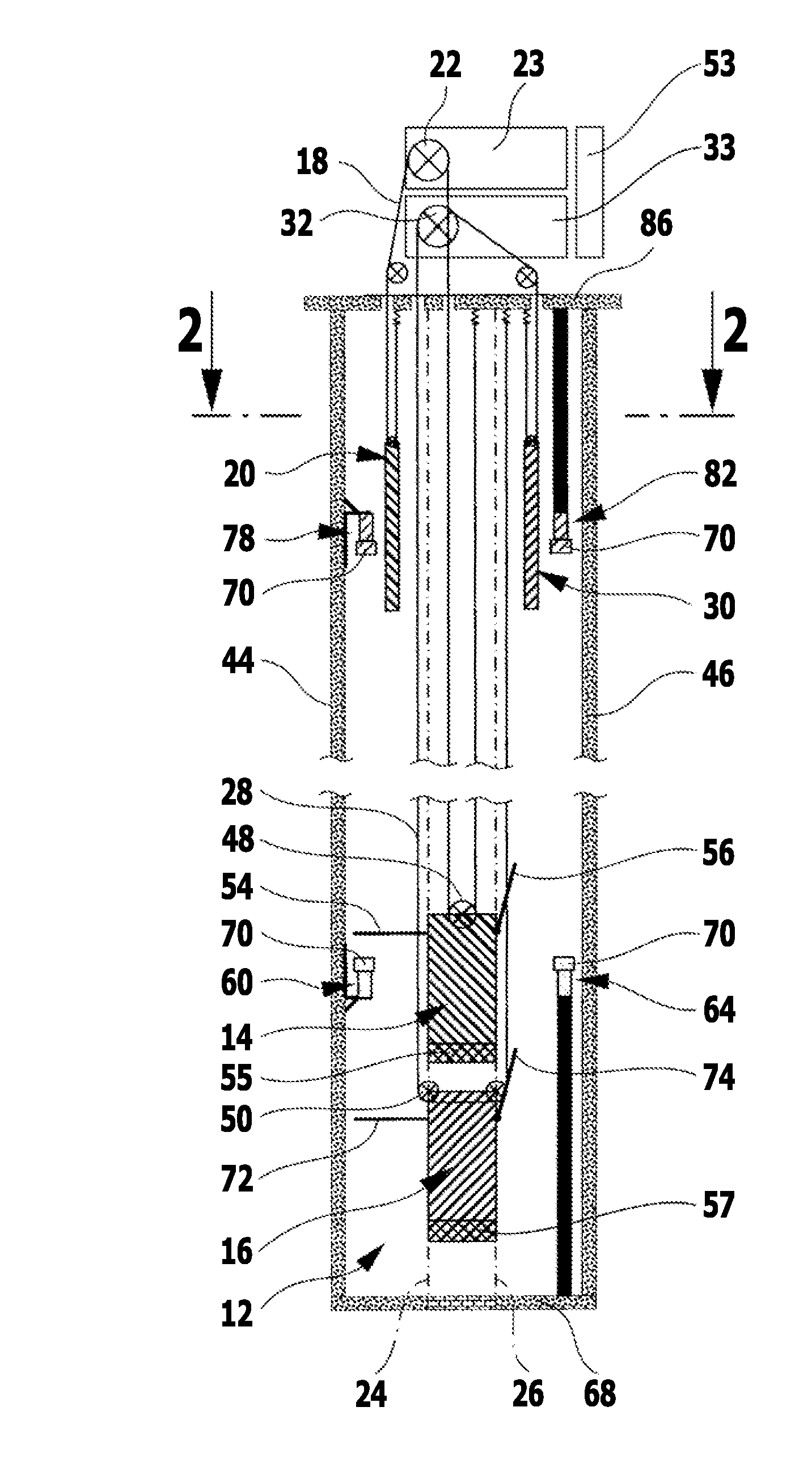
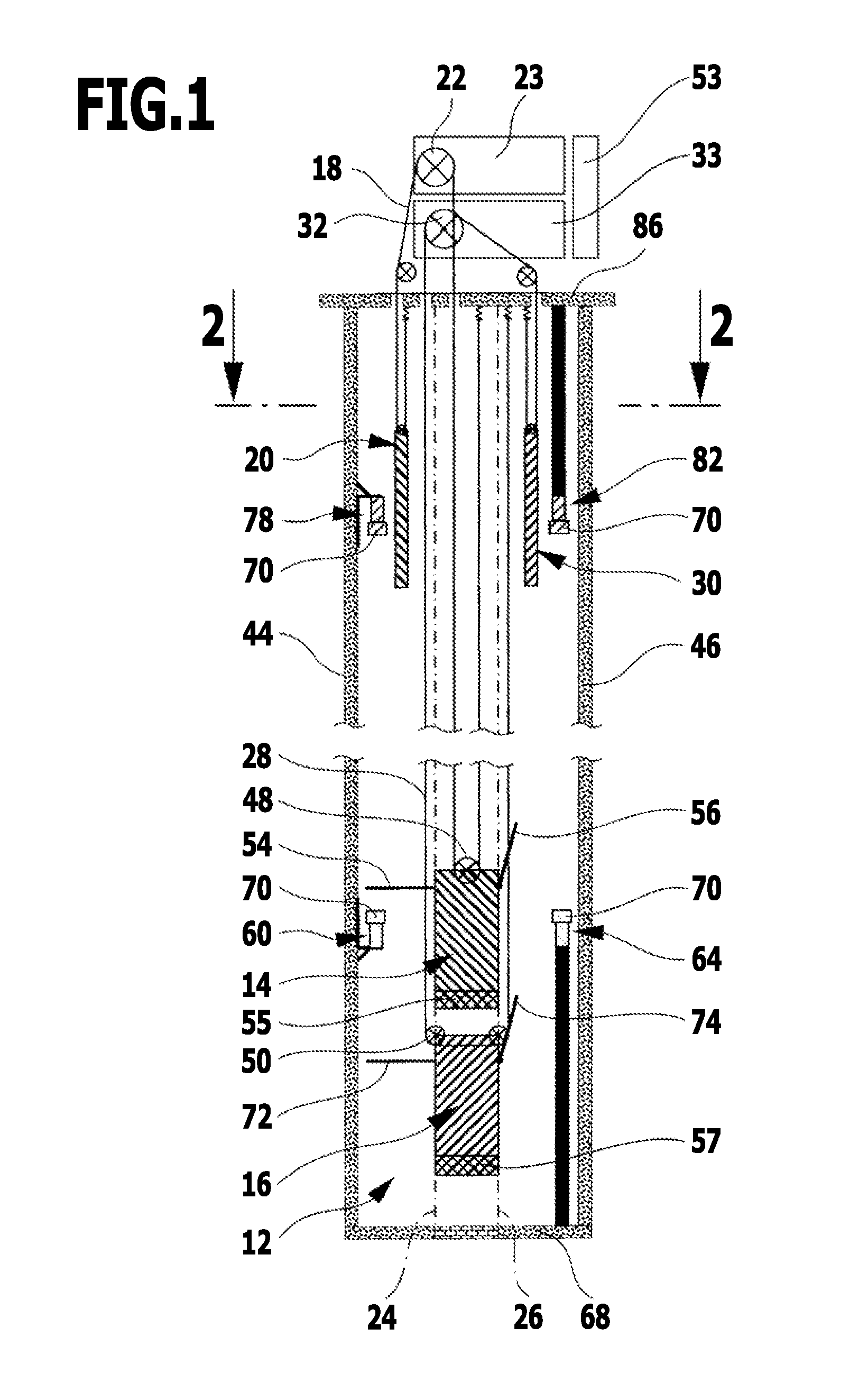
[0069]an elevator installation in accordance with the invention, generally denoted by reference numeral 100, is shown in FIG. 3. This is largely identical in configuration to the elevator installation 10 explained above with reference to FIGS. 1 and 2. The same reference numerals as in FIGS. 1 and 2 are, therefore, used for identical components in FIG. 3, and regarding these components reference is made to the above explanations in order to avoid repetitions.

[0070]The elevator installation 100 differs from the elevator installation 10 in that the buffer elements 70 are not arranged on the retaining elements 60, 64, 78 and 82, but instead the buffer elements 70, in the elevator installation 100 shown in FIG. 3, are held on the stop elements 54, 56 and 72, 74. Again, when the stop elements 54, 56 strike the retaining elements 60 and 64, respectively, and when the stop elements 72 and 74 strike the retaining elements 78 and 82, the impact energy can be absorbed by the buffer elements 7...

third embodiment

[0072]an elevator installation 110 in accordance with the invention, which is largely identical in construction to the elevator installations 10 and 100 explained above, is shown in FIGS. 4 and 5. Identical reference numerals will, therefore, be used for identical components in the elevator installation 110 shown in FIGS. 4 and 5 and also in the elevator installation 130 shown in FIG. 6 and explained below, as in FIGS. 1, 2 and 3, and regarding these components reference is made to the above explanations in order to avoid repetitions.

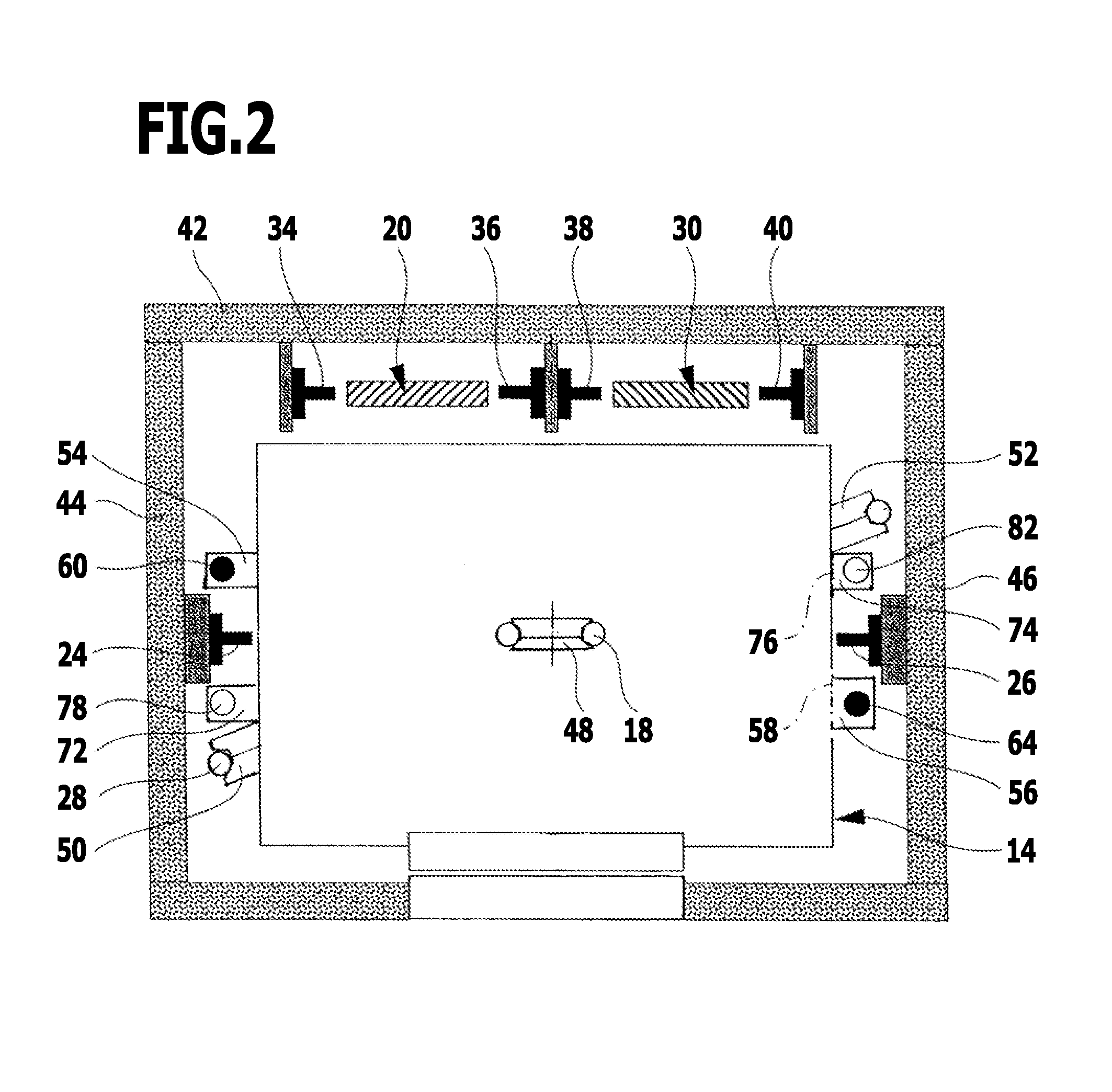
[0073]The elevator installations 110 and 130 are shown in FIGS. 4 and 6 in sectional views, which run perpendicularly to the shaft rear wall 42 and thereby make the arrangement of the counterweights 20, 30 alongside each other and the region between the counterweights 20, 30 and the shaft rear wall 42 clearer. In the elevator installations 110 and 130, differently from the elevator installations 10 and 100 explained above, stop elements are not arranged...


PUM


Abstract

An elevator installation is provided. The installation includes a shaft in which at least two cars are arranged above one another and are movable vertically separately. Each car has a drive device and a brake device. A safety device is provided for monitoring the cars. At least one travel path limiting device is provided, comprising at least one stop element arranged on at least a first car and an associated retaining element arranged in the shaft. In a stop position, the stop element protrudes laterally from the car and interacts with the associated retaining element. All other cars movable in the shaft may pass this retaining element unobstructed. The brake device or its braking action is deactivatable if the car falls below a limit speed, and the stop and retaining elements may brake the car to a standstill at speeds up to at most the limit speed.

Description

[0001]This application is a continuation of international application number PCT / EP2011 / 060347 filed on Jun. 21, 2011 and claims the benefit of German application number 10 2010 030 436.0 filed on Jun. 23, 2010, which are incorporated herein by reference in their entirety and for all purposes.BACKGROUND OF THE INVENTION[0002]The invention relates to an elevator installation with a shaft in which at least two cars are arranged one above the other and are movable vertically up and down separately from each other, each car having a drive device associated therewith for moving the car, and each car having a brake device arranged thereon, and with a safety device for monitoring the operating behavior of the cars, and with at least one travel path limiting device, which comprises at least one stop element arranged on a car and a retaining element arranged in the shaft and interacting with the stop element, for limiting the travel path of the car.[0003]The use of at least two cars which ar...

Claims


Application Information

Patent Timeline
Patent Type & Authority Applications(United States)
IPC IPC(8): B66B9/00
CPCB66B5/0031B66B9/00B66B5/286B66B5/28B66B5/00
Inventor ALTENBURGER, BERNDVON SCHOLLEY, HANS-FERDINANDZERELLES, HOLGER
Owner THYSSENKRUPP ELEVATOR AG (DE)
Why Eureka
Try Eureka