Transporting system

Active Publication Date: 2013-11-21
DEMATIC
View PDF18 Cites 1 Cited by
  • Summary
  • Abstract
  • Description
  • Claims
  • Application Information

AI Technical Summary

Benefits of technology

[0018]In a further variation, the shuttle or satellite vehicle travels from a transfer machine, such as, for example, a rack serving machine, into the different sections of a storage system. The transfer within the storage aisle itself is then effected via a transfer machine which travels to the respective storage section. The shuttle itself then travels into the storage section where it sets down the load or picks it up and then travels to the transfer machine. The stops are also provided at the end of th

Problems solved by technology

The type of buffer or stop of the prior art does not offer sufficient security in all cases.
In addition, construction thereof is troublesome in that the pivotable stop elements or levers must be provided on each rail end, which is associated with complex cabling and control and monitoring.
It is also unclear what happens in the event of a problem with the stop eleme

Method used


Image

  • Transporting system
  • Transporting system
  • Transporting system

Examples


Embodiment Construction

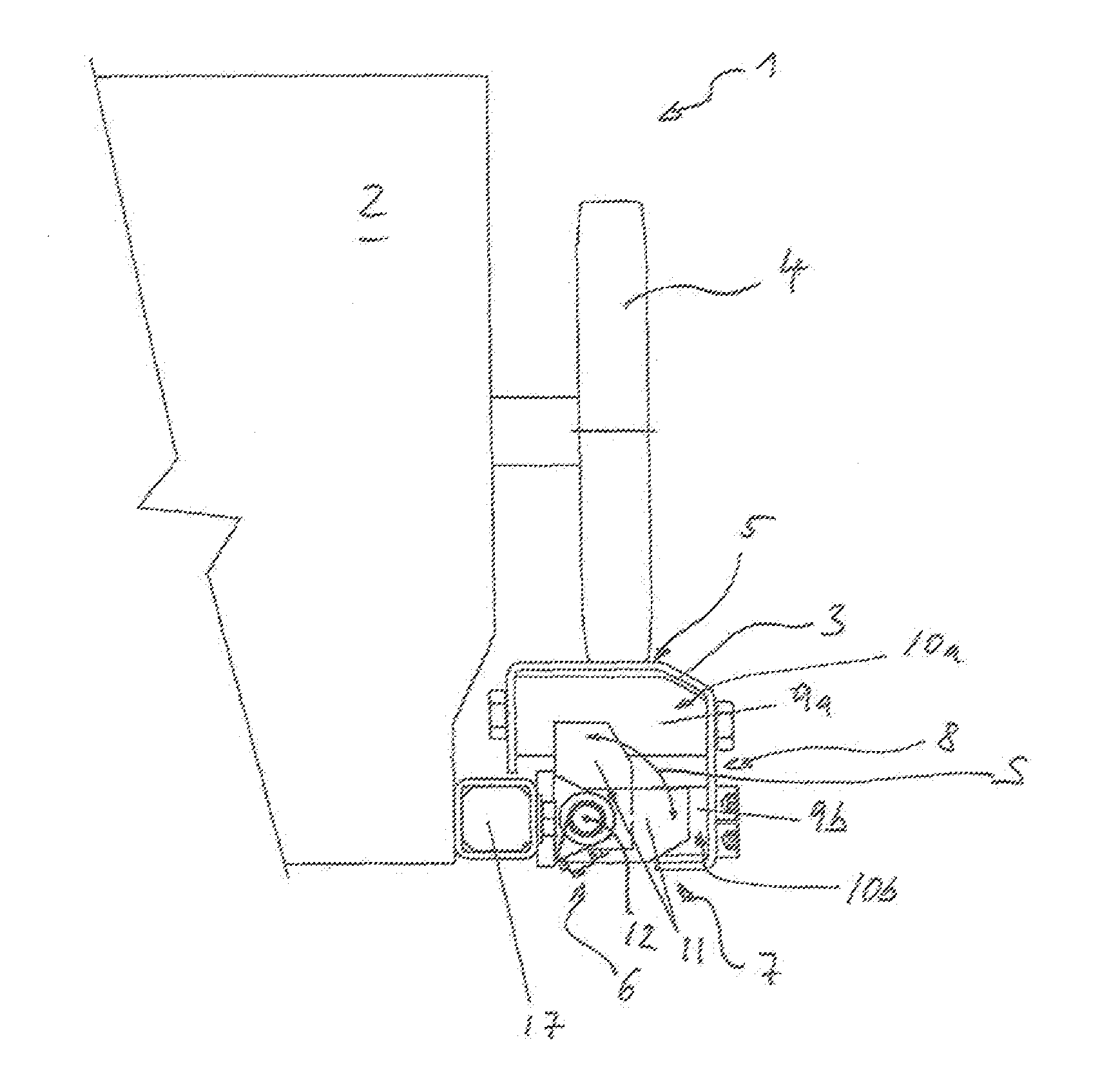
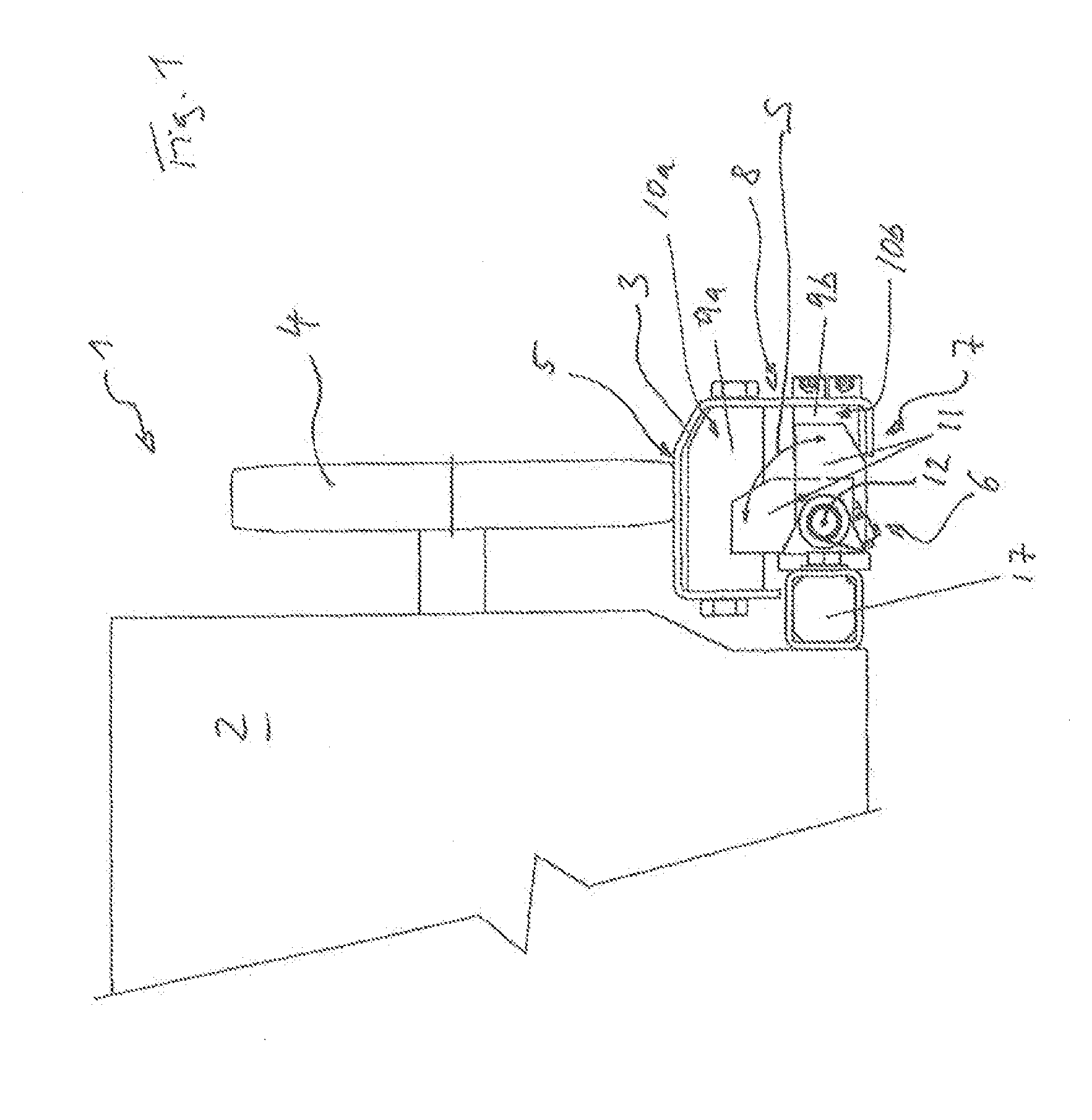
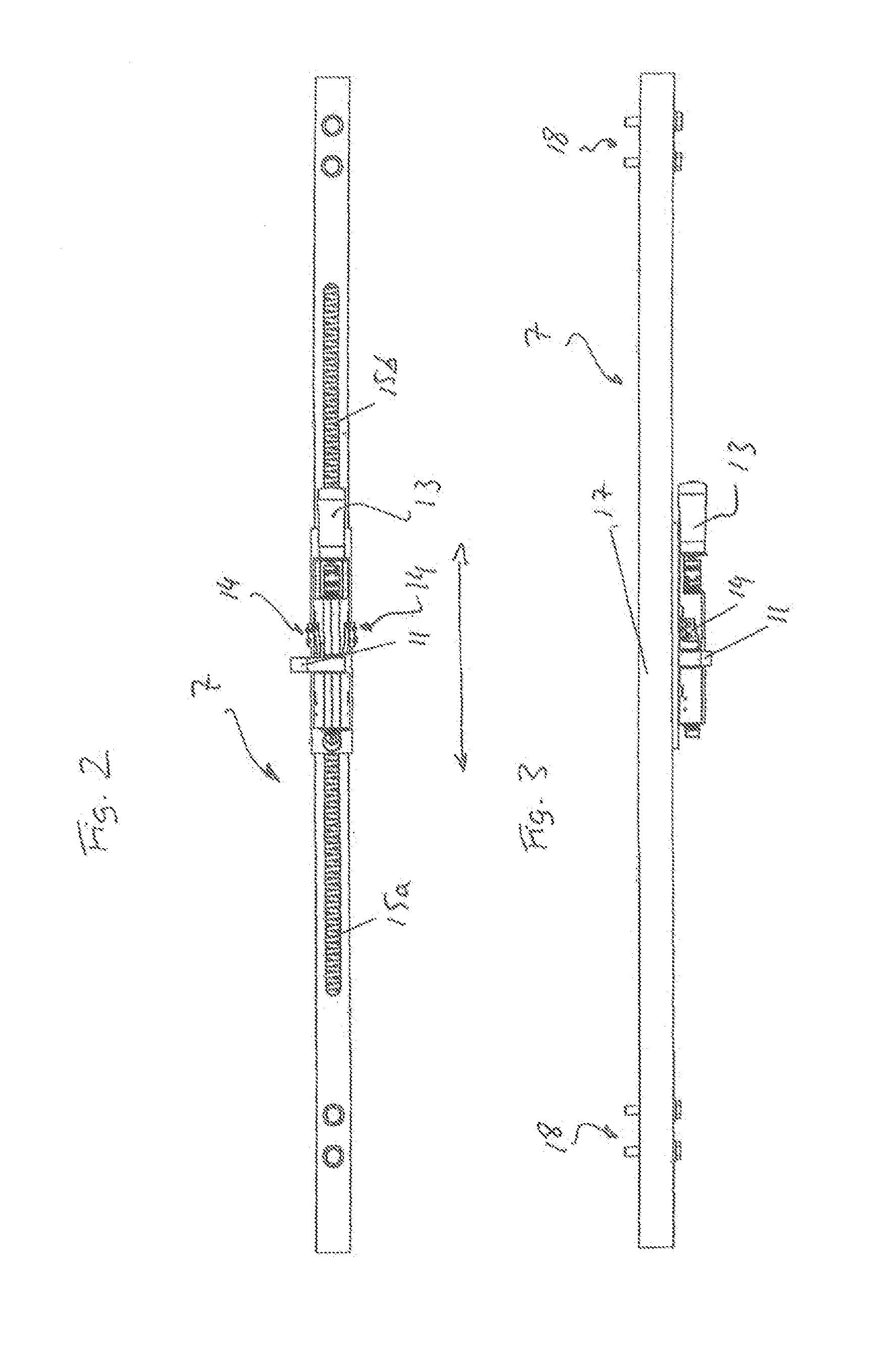
[0025]FIGS. 1 to 3 show a shuttle or the satellite, designated as a whole by 1, of a storage and transport system which conveys goods and / or containers of varying sizes along the travel path. For this purpose, it includes a load-picking-up means, not shown, which picks up or sets down the goods and / or containers. The loading space of the shuttle 1 is between a front and rear region, the mutual spacing of which can be adjusted according to the goods being transported. In the front region or rear region, the housing 2 is formed in a box-like manner in each case and accommodates the on-board electronics, super-capacitors for short-term power supply and to cover power peaks, radio equipment, etc.

[0026]The actual power supply and charging of the super-capacitors is effected via current collectors which “tap” a contact line. The contact line is conventionally formed either as a separate line or by the travel rail 3. The travel rail 3 is formed by two parallel rails laterally defining the ...


PUM


Abstract

The invention relates to an in-house track-bound transporting system with self-propelling carriages that move on rails. The system has stoppers to prevent said carriages from crossing over open rail ends or track borders, and the system is provided with stops. The stoppers collide with the stops in order to prevent a crossing-over, said stops having first and second fixed stop elements. The stoppers can be moved between a first crossing-over position and a second crossing-over position such that the first stop elements can be crossed over in the first crossing-over position of the stoppers, and the second stop elements can be crossed over in the second crossing-over position of the stoppers, wherein the first stop elements cannot be crossed over in the second crossing-over position of the stoppers, and the second stop elements cannot be crossed over in the first crossing-over position of the stoppers.

Description

CROSS REFERENCE TO RELATED APPLICATION[0001]The present application claims the priority benefits of International Patent Application No. PCT / EP2012 / 050826, filed on Jan. 20, 2012, which is hereby incorporated herein by reference in its entirety.BACKGROUND OF THE INVENTION[0002]The invention relates to an in-plant rail-bound transport system with shuttles that travel on rails, wherein the system has stop bars to secure against overrunning of open rail ends or boundaries of travel paths, and is provided with stops, wherein stop bars engage the stops to prevent such overrunning.[0003]Transport systems of this type are used both in the warehousing area and also in the production area and comprise shuttles. These are usually single-level rack serving machines, or so-called satellite vehicles or autonomous vehicles, which transport goods, with or without containers, and place them into, and remove them from, storage in the warehousing and production areas.[0004]At the ends of the rail lin...

Claims


Application Information

Patent Timeline
IPC IPC(8): B61K7/16
CPCB61K7/16B65G1/065
Inventor YAMASHITA, SHIN
Owner DEMATIC
Why Eureka
Try Eureka