Expandable clamp with interlacing jaw heads

Inactive Publication Date: 2013-05-16
CHEN DEMING +1
View PDF19 Cites 14 Cited by
  • Summary
  • Abstract
  • Description
  • Claims
  • Application Information

AI Technical Summary

Benefits of technology

[0012]Comparing with conventional symmetrical jaw expandable clamps, the jaw necks of the invention do not have to be less than a half of the slit in the frame member but has a thickness of near a whole width of the slit. A strength of the jaw necks is significantly

Problems solved by technology

All conventional expandable clamps have a pair of opposing jaws which are basically symmetrical and face a common problem: a largest width of the longitudinal central slit defined in a frame member is decided by a cross-sectional area of the frame member.
However, for opposing symmetrical conventional jaw heads and jaw necks, a thickness thereof cannot be limitlessly decrease for sake of structure strength.
As a result, conventional expandable clamps are only applicable on “thick” frame membe

Method used


Image

  • Expandable clamp with interlacing jaw heads
  • Expandable clamp with interlacing jaw heads
  • Expandable clamp with interlacing jaw heads

Examples


Example

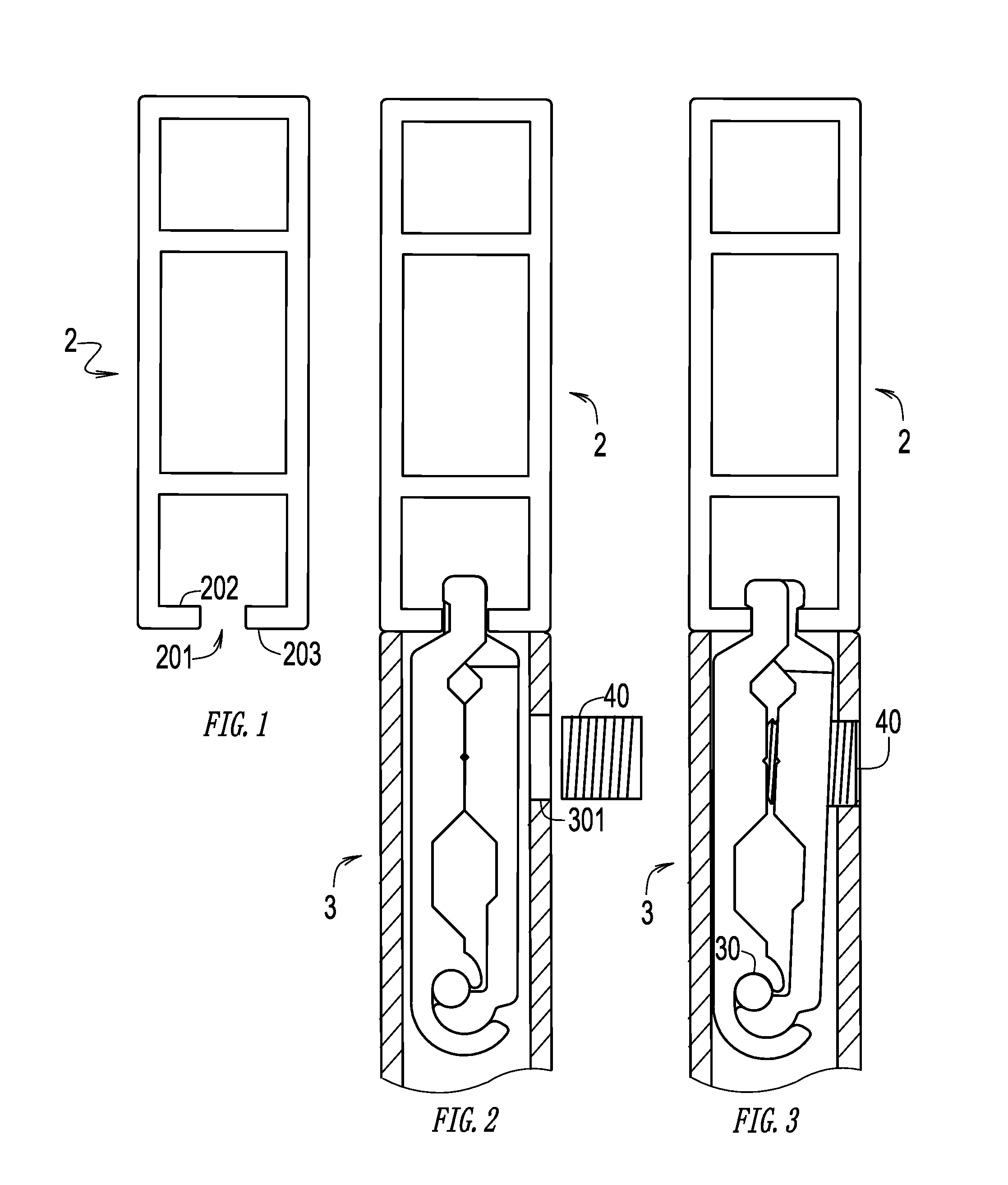
[0025]Shown in FIG. 1 is the preferred embodiment of an expandable clamp 1 of the invention linking a first frame member 2 and a second frame member 3. The first frame member 2 has at least one slit 201 defined therein, forming two opposing flange 202 and 203. The expandable clamp 1 is contained in the second frame member 3 and longitudinally fixed with respect to the second frame member 3 with a set screw 40.

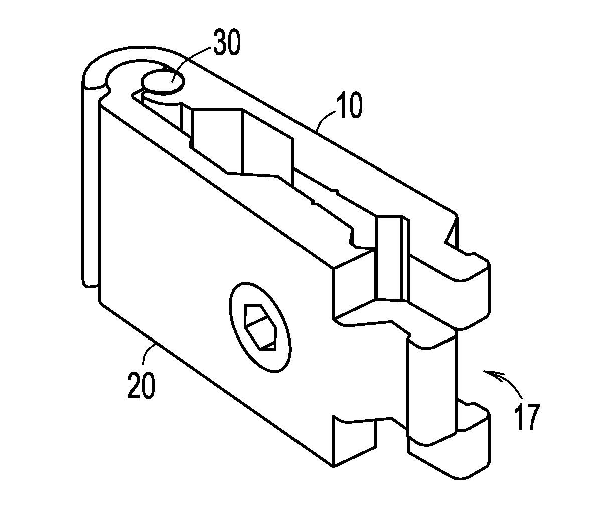
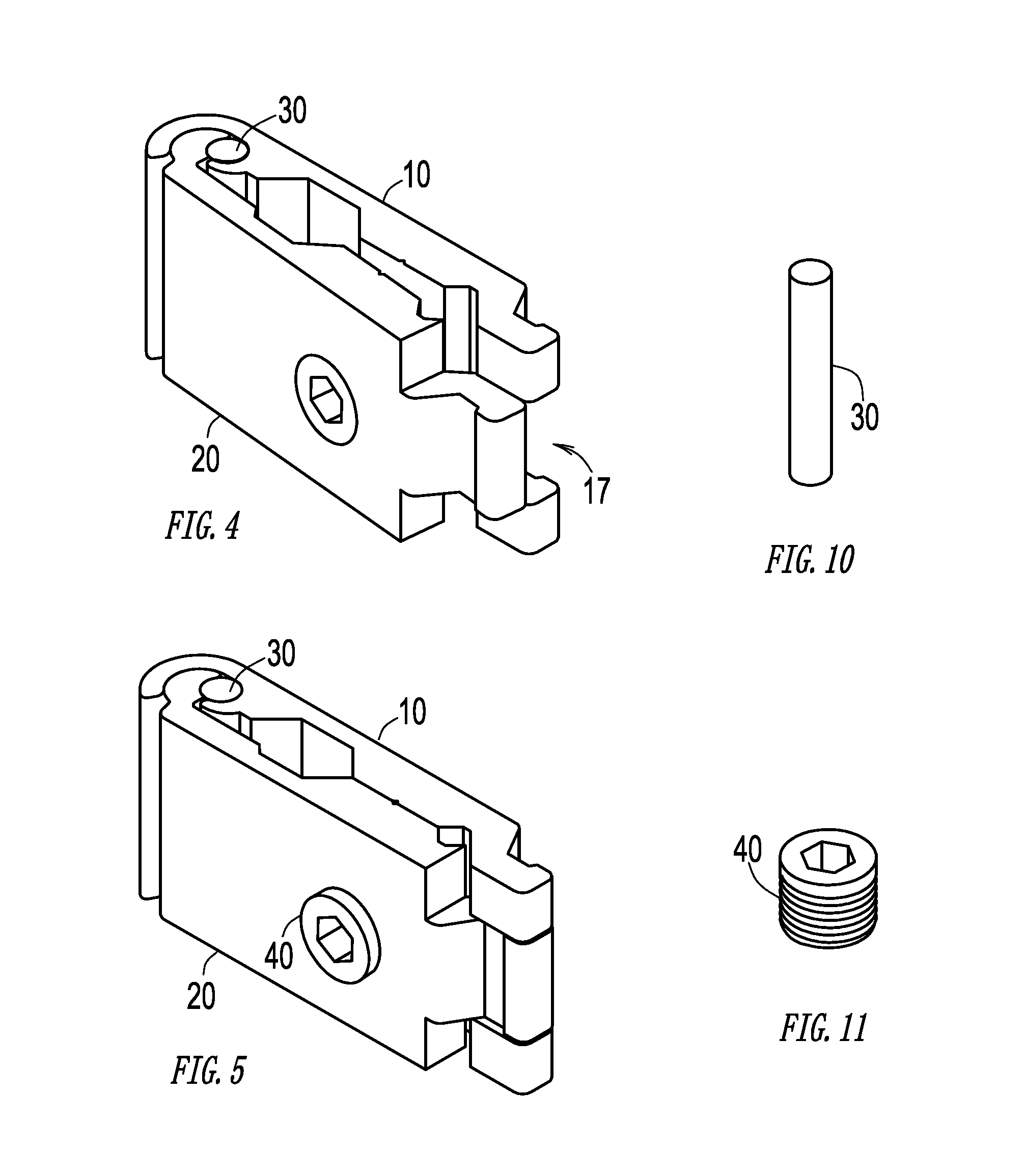
[0026]With reference to FIGS. 3 to 8, the expandable clamp 1 has a first jaw 10 and a second jaw 20 each has a rear end 11 and 21 pivotally linking together. The first jaw 10 has a first inner face 12 facing the second jaw 20 and an opposing first outer face 13. The second jaw 20 has a second inner face 22 facing the first jaw 10 and an opposing second outer face 23. The linking of the rear ends 11 and 21 is a conventional techniques and able to be any way that is pivotal. Shown in the Figs. is a usually way that is called quick assembly coupling in which one rear end 21 is a h...


PUM


Abstract

An expandable clamp having a first jaw and a second jaw each having a rear end pivotally linking together, and an elastic member urging the first and the second jaws in a closing position in which the first and the second jaws touch each other. The fist jaw further has a first shoulder inclining inward, on which two first jaw necks are formed, leaving a space therebetween. A first jaw head being formed on each first jaw neck extending outward. The second jaw has a second shoulder inclining inward, on which one second jaw neck is formed. A second jaw head is formed on the second jaw neck extending outward. In the closing position, the first jaw necks and jaw heads are interlacing with respect to the second jaw neck and jaw head.

Description

CROSS-REFERENCE TO RELATED APPLICATIONS[0001]Not ApplicableSTATEMENT REGARDING FEDERALLY SPONSORED RESEARCH OR DEVELOPMENT[0002]Not ApplicableINCORPORATION-BY-REFERENCE OF MATERIAL SUBMITTED ON A COMPACT DISC[0003]Not ApplicableBACKGROUND OF THE INVENTION[0004]1. Field of the Invention[0005]The invention relates to an expandable clamp with interlacing jaw heads for modular frame assembly, and more particularly, to the expandable clamp having a stronger structure or smaller volume.[0006]2. Description of Related Art[0007]Modular panel frame assembly system is widely used in applications as office partitions, display racks, and window supports. A typical conventional expandable clamp for modular panel frame assembly is taught in U.S. Pat. No. 4,907,388. The clamp has opposing jaws that are always separated from each other by a substantial space. The frame members have at least one longitudinal central slit which is able to be engaged the by expandable clamp.[0008]All conventional expa...

Claims


Application Information

Patent Timeline
IPC IPC(8): F16B2/04
CPCY10T403/7041F16B7/0473
Inventor CHEN, DEMINGXUE, HAIYAN
Owner CHEN DEMING
Why Eureka
Try Eureka