
Transdermal Sampling and Analysis Device

a technology which is applied in the field of transdermal sampling and analysis device, can solve the problems of inconvenient procedure, inconvenient operation, and inability to accurately determine the effect of the procedure, and achieve the effect of altering the permeability of the stratum corneum

Active Publication Date: 2013-05-16
CLINITECH LLC +2
View PDF6 Cites 23 Cited by
  • Summary
  • Abstract
  • Description
  • Claims
  • Application Information

AI Technical Summary

Benefits of technology

The patent describes a way to extract biological samples from the skin through a process called transdermal extraction. This process is safe and non-invasive, and uses a disruptor unit to create temporary holes in the skin that allow interstitial fluid to flow and be collected for analysis. The collected samples can then be used with biological reactive elements to sense certain properties of the samples. Channel and reservoir configurations are also used to help deliver the collected samples to the sensors. Overall, this patent provides a technical solution for safely and accurately collecting biological samples for analysis.

Problems solved by technology

Conventional methods for obtaining biological samples are typically painful and invasive.
This procedure may be uncomfortable, painful, and especially irritating when it has to be performed multiple times a day in the case of diabetics.
In addition to pain and discomfort, there are other undesirable side effects associated with these invasive tissue extraction techniques.
For example, diabetics who also suffer from hemophilia face the danger of severe hemorrhage every time they have to test their blood glucose levels using invasive procedures.
In another example, these invasive procedures expose immuno-compromised diabetics to increased chances of local or systemic infections.
To obtain these larger biological samples, painful and invasive procedures must be employed, which are not desirable.

Method used


Image

  • Transdermal Sampling and Analysis Device
  • Transdermal Sampling and Analysis Device
  • Transdermal Sampling and Analysis Device

Examples


Embodiment Construction

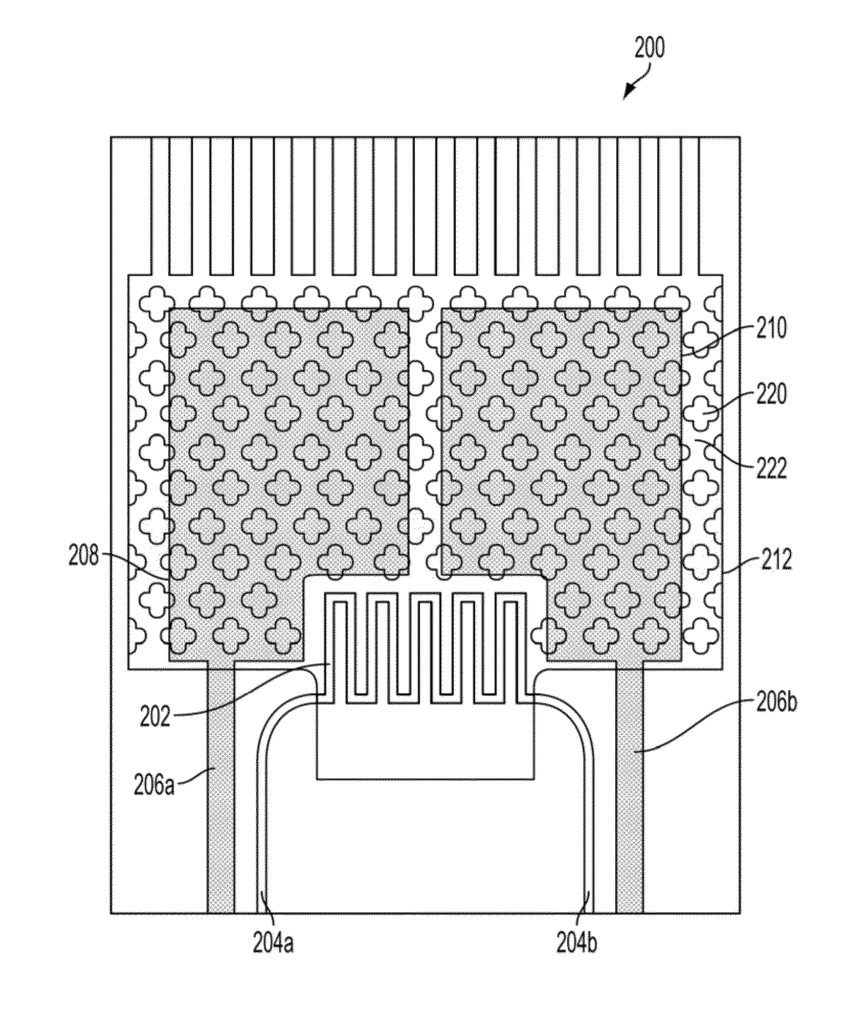
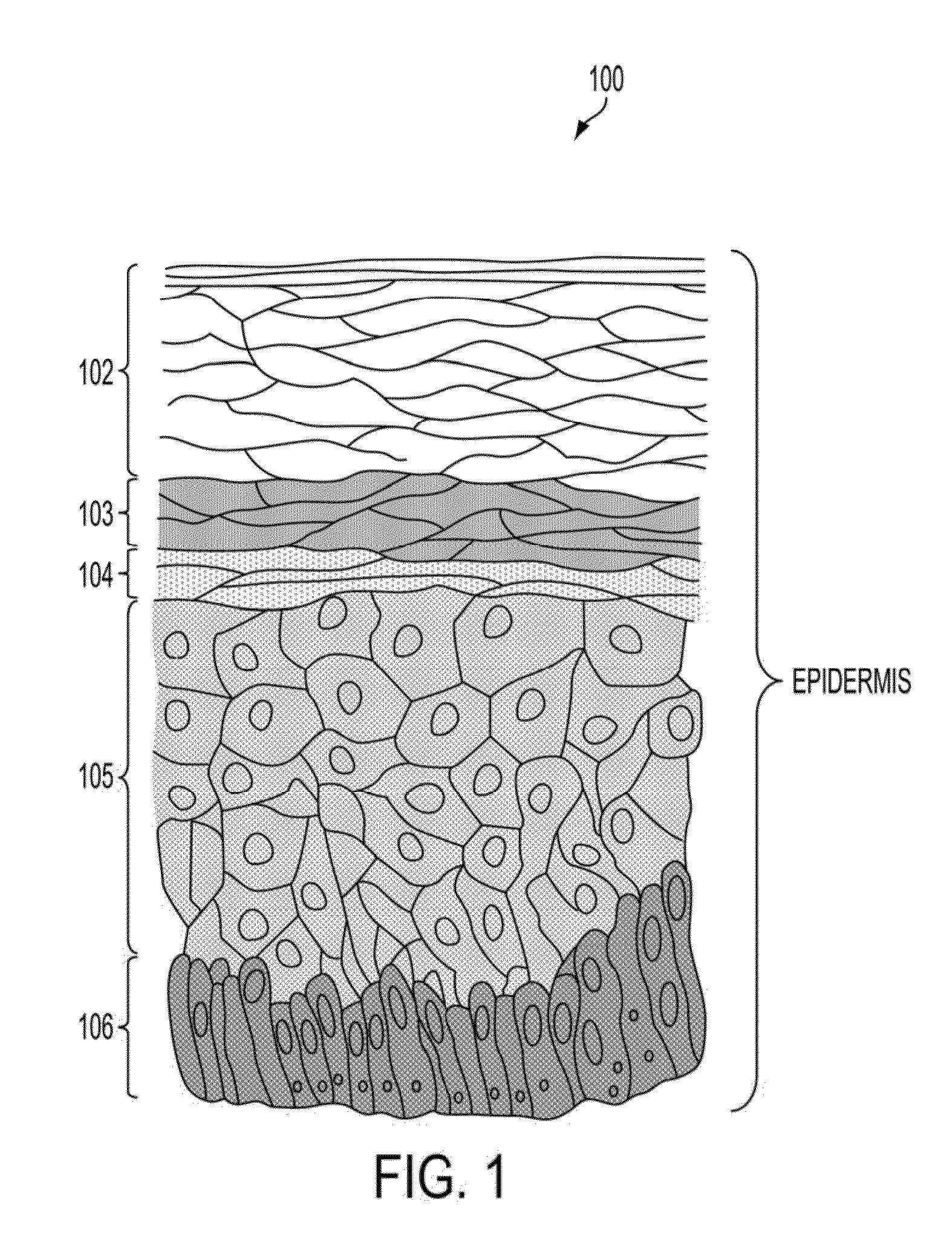
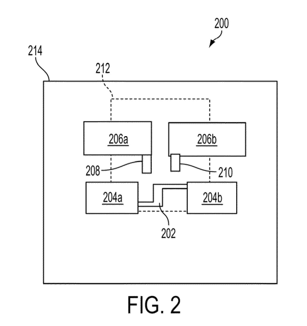
[0042]The various embodiments will be described in detail with reference to the accompanying drawings. Wherever possible, the same reference numbers will be used throughout the drawings to refer to the same or like parts. References made to particular examples and implementations are for illustrative purposes, and are not intended to limit the scope of the invention or the claims.

[0043]The various embodiments will be described in detail with reference to the accompanying drawings. Wherever possible, the same reference numbers will be used throughout the drawings to refer to the same or like parts. References made to particular examples and implementations are for illustrative purposes, and are not intended to limit the scope of the disclosure or the claims. Alternate embodiments may be devised without departing from the scope of the disclosure. Additionally, well-known elements of the disclosure will not be described in detail or will be omitted so as not to obscure the relevant det...


PUM


Abstract

Transdermal sampling and analysis device, method and system are provided for non-invasively and transdermally obtaining biological samples from a subject and determining levels of analytes of the obtained biological samples. The transdermal sampling and analysis device, method and system may cause disruption to the skin cells to create capillary-like channels from which biological samples may flow to the transdermal sampling and analysis device. The transdermal sampling and analysis device, method and system may collect the biological samples in a reservoir and transport the biological samples to a sensing chamber. The sensing chamber may contain at least two sensing electrodes coated with a biologically reactive element which reacts with the transported biological sample. The sensing chamber may be configured to mitigate the formation of air bubbles which may impede the transport and distribution of the biological sample across the entirety of the sensing chamber.

Description

RELATED APPLICATIONS[0001]This application is a continuation-in-part of U.S. patent application Ser. No. 13 / 294,368 entitled “Transdermal Sampling and Analysis Device,” filed on Nov. 11, 2011, which claims priority to U.S. Provisional Patent Application No. 61 / 121,982 filed on Dec. 10, 2010, the entire contents of which are hereby incorporated by reference for all purposes.BACKGROUND[0002]Effective diagnoses and treatment of diseases depend on accurate monitoring of the current physiological state of a subject. Monitoring the concentration of molecules in the body is an example of a method for determining the physiological state. For example, diabetics must actively monitor their body's glucose levels to treat and prevent potentially life threatening conditions such as hypo- or hyperglycemia.[0003]Monitoring the internal physiological state of a subject requires a two step process. First, biological samples must be obtained from the body of the subject. Second, the sample must be an...

Claims


Application Information

Patent Timeline
Patent Type & Authority Applications(United States)
IPC IPC(8): A61B5/157A61B5/1491A61B5/1477
CPCA61B5/150122A61B2562/0295A61B5/14532A61B5/1486A61B5/150022A61B5/150076A61B5/150358A61B5/150412A61B5/150854A61B5/150862A61B5/15087A61B5/150946A61B5/150984A61B5/15134A61B5/157A61B5/0022
Inventor CURRIE, JOHN F.MARCANIO, JOSEPH A.VIDALIS, JOSEPH J.
Owner CLINITECH LLC
Learn More