
Self-deploying locking screw retention device

Active Publication Date: 2013-05-16
TITAN SPINE
View PDF3 Cites 27 Cited by
  • Summary
  • Abstract
  • Description
  • Claims
  • Application Information

AI Technical Summary

Benefits of technology

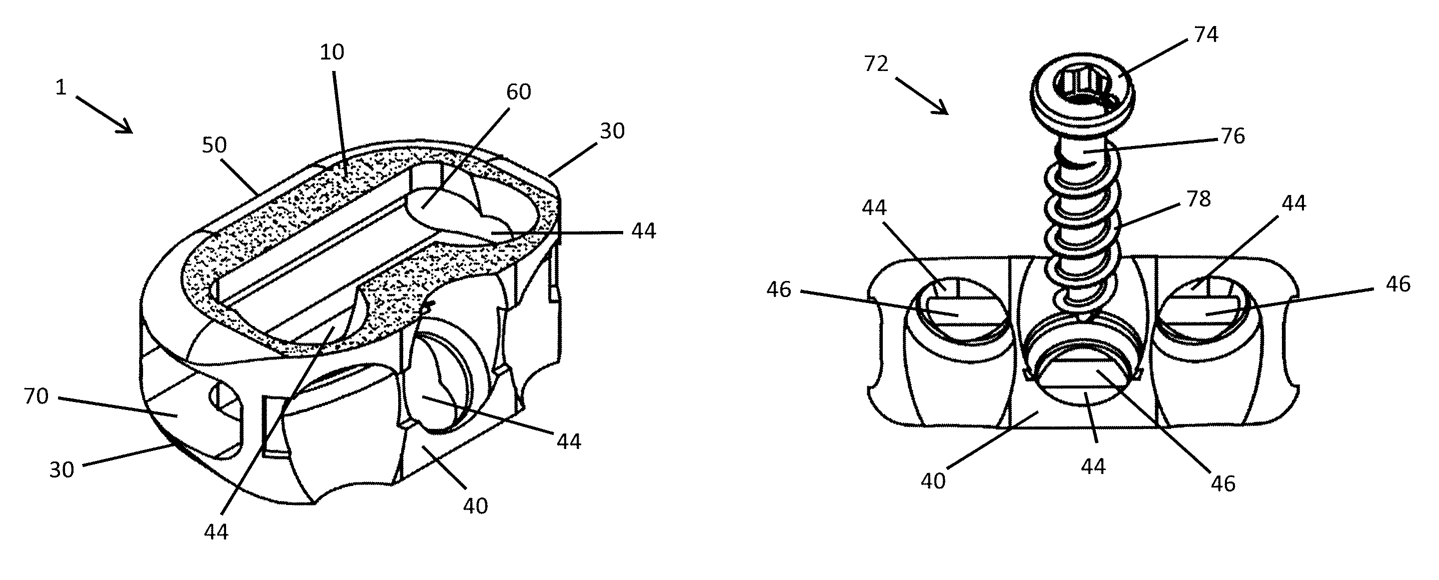
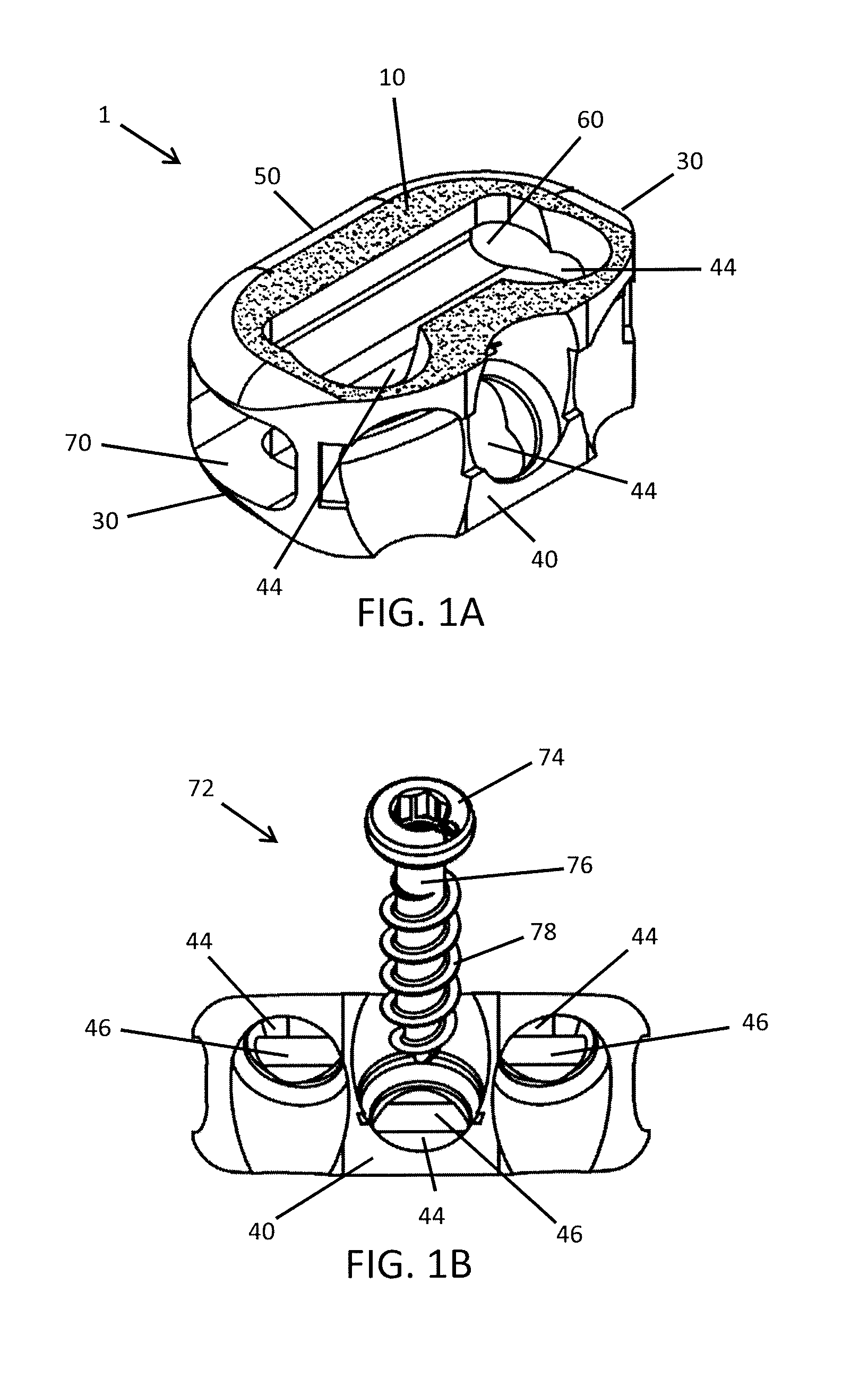
The present invention provides interbody spinal implants with screws that have a self-deploying screw retention member. This design ensures that the screws are secured without changing the loading of the implant and adding stability and expulsion resistance. The screws and self-deploying retention mechanisms work in conjunction with the fusion-enhancing implant and the bone structure-preserving surgical technique to reduce the potential for joint motion-induced loosening and back out of the screws. The screw retention members are self-deploying and integrated with the screws, making it easier to use and reducing the likelihood of additional fragments in the disk space in the unlikely event of screw failure. The screws may be fastened to the implant and the bone with the screw retention members in a contracted or retracted position, and after implantation, the screw retention members expand to lock the screws in place and prevent them from backing out of position.

Problems solved by technology

In particular, the locations and alignment of the screws (e.g., based on screw insertion path), final location within the disk space, and friction between the integration surface(s) of the implant and the preserved vertebral endplates reduce the potential for joint motion-induced loosening and back out of the screws.

Method used


Image

  • Self-deploying locking screw retention device
  • Self-deploying locking screw retention device
  • Self-deploying locking screw retention device

Examples


Embodiment Construction

[0056]The present invention provides for spinal implants having screws with a self-deploying screw retention member. The screw retention member is designed to open, extend, or self-deploy, for example, once the retention member reaches near or about body temperature.

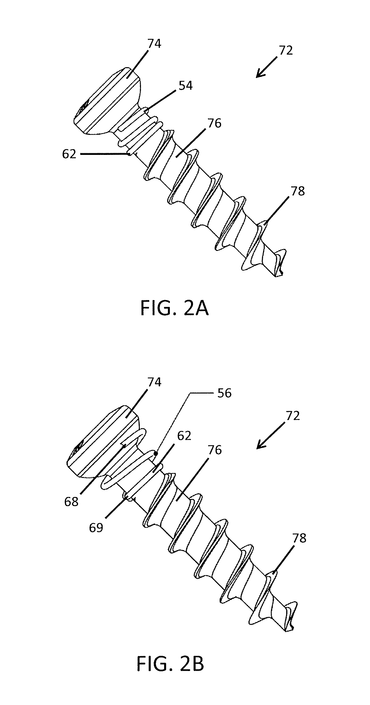
[0057]According to one embodiment, the present invention provides a screw assembly for a spinal implant comprising a screw having a head and a shaft and a screw retention member (e.g., a coiled spring or a collar with a plurality of tabs) positioned beneath the head of the screw and substantially surrounding the shaft of the screw. The screw retention member may have a contracted or retracted position adapted for inserting the screw through at least one hole in the spinal implant and an expanded position adapted for retaining the screw within the at least one hole in the spinal implant.

[0058]Screw Retention Member

[0059]The screw includes at least one self-deploying retention member. As used in this document, “self-deploy...


PUM


Abstract

A screw assembly and a spinal implant. The screw assembly includes a screw with a head and a shaft where a screw retention member is positioned beneath the head of the screw and substantially surrounds the shaft of the screw. The screw retention member is formed from a temperature-sensitive material. The screw retention member has a first contracted position adapted for inserting the screw through at least one hole in the spinal implant and a second expanded position adapted for retaining the screw within the at least one hole in the spinal implant. The screw retention member may be in the form of a coiled spring or a collar having a plurality of tabs.

Description

CROSS REFERENCE TO RELATED APPLICATIONS[0001]This application is a continuation-in-part of U.S. patent application Ser. No. 13 / 572,077, which is a continuation of U.S. patent application Ser. No. 12 / 151,198, filed on May 5, 2008, which issued as U.S. Pat. No. 8,262,737, which is a continuation-in-part of U.S. patent application Ser. No. 11 / 123,359, filed on May 6, 2005, and issued as U.S. Pat. No. 7,662,186. The contents of all prior applications are incorporated by reference into this document, in their entirety and for all purposes.TECHNICAL FIELD[0002]The present invention relates generally to interbody spinal implants and, more particularly, to spinal implants having bone screws with a self-deploying screw retention device.BACKGROUND OF THE INVENTION[0003]In the simplest terms, the spine is a column made of vertebrae and discs. The vertebrae provide the support and structure of the spine while the spinal discs, located between the vertebrae, act as cushions or “shock absorbers.”...

Claims


Application Information

Patent Timeline
IPC IPC(8): A61F2/44
CPCA61F2/442A61F2310/00149A61F2002/30454A61F2002/30469A61F2002/30472A61F2002/30481A61F2002/305A61F2002/30507A61F2002/30892A61F2002/30906A61F2002/30925A61F2002/4475A61F2002/448A61F2002/4629A61F2310/00017A61F2310/00023A61F2/30965A61F2/4465A61F2002/2817A61F2002/2835A61F2002/30014A61F2002/30133A61F2002/30405A61F2002/30604A61F2002/30772A61F2002/30785A61F2002/30836A61F2002/30973A61F2002/30092A61F2002/3084A61F2002/30443A61F2002/30444A61F2002/30566A61F2002/30574A61F2002/30576A61F2002/30578A61F2002/30787A61F2310/00047A61F2310/00071A61F2310/00077A61F2310/00083A61F2310/00107A61F2002/30441A61B17/8033A61F2002/30433A61F2002/30451A61F2002/30593A61B17/844A61F2002/30484A61F2002/30039A61F2002/30495
Inventor PATTERSON, CHAD J.ULLRICH, JR., PETER F.
Owner TITAN SPINE
Learn More