

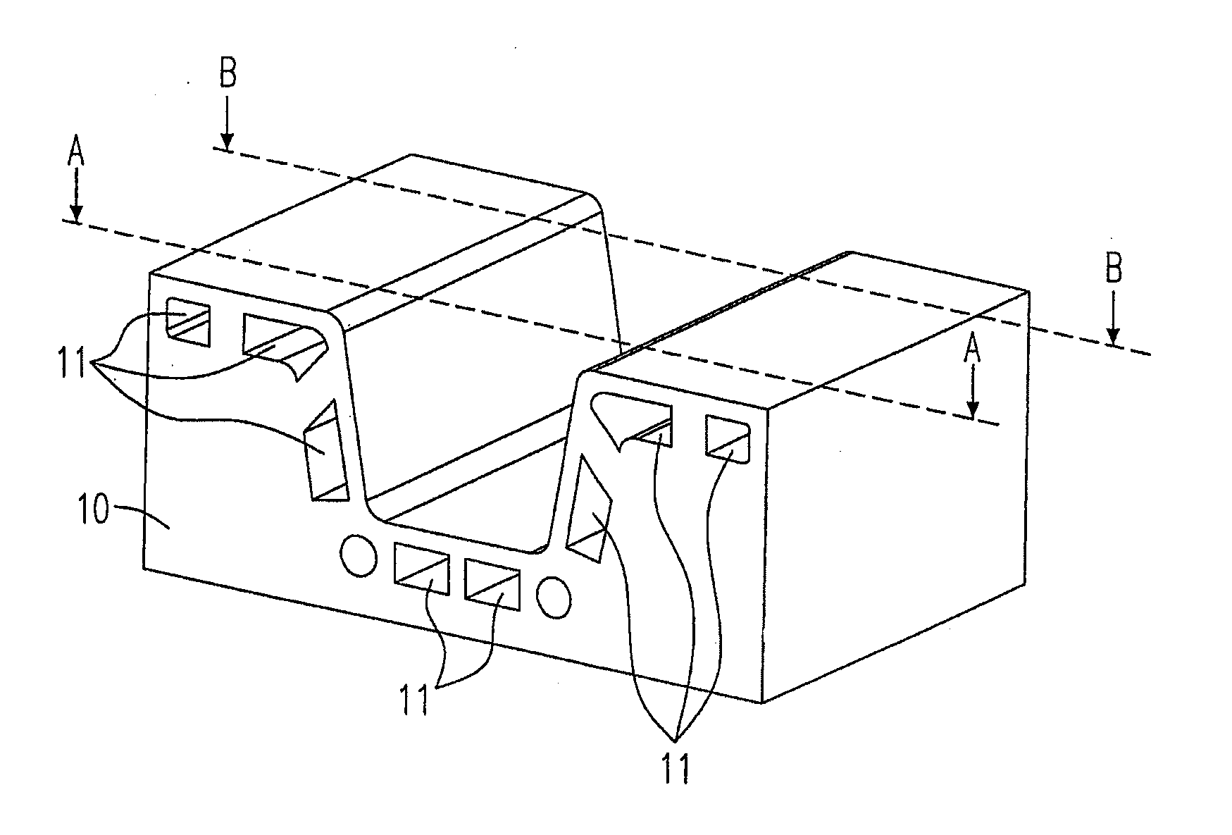
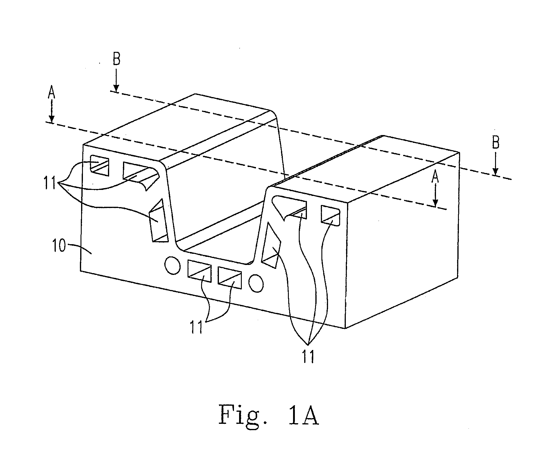
Mold and method for sectionally adjusting cooling efficiency of the mold
a cooling efficiency and mold technology, applied in the field of molds and cooling efficiency sections, can solve the problems of ineffective temperature control during the hot-stamping process using molds, improvement of homogeneous heat transfer, and inhomogeneous cooling effect, so as to achieve different mechanical properties such as hardness and strength of products, and adjust the cooling efficiency or heat dissipation rate.
- Summary
- Abstract
- Description
- Claims
- Application Information
AI Technical Summary
Benefits of technology
Problems solved by technology
Method used
Image

Examples
embodiment 1
[0027]2. The method of embodiment 1, wherein the mold includes a hot-stamping die.
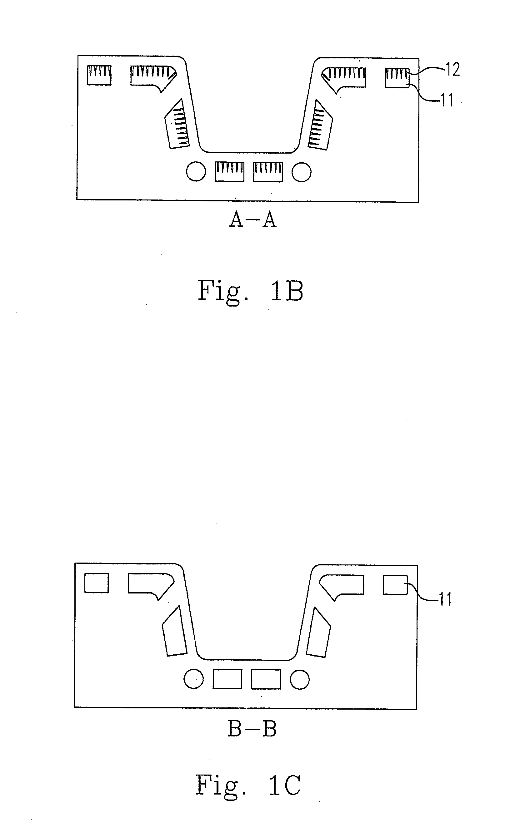
[0028]3. The method of embodiment 1, wherein the heat-dissipating element includes at least one of a fin and a foil.
[0029]4. The method of embodiment 1, wherein the step of adjusting the first and the second heat-dissipating inner surface areas is performed by increasing at least one of the first heat-dissipating inner surface area and the second heat-dissipating inner surface area.
[0030]5. The method of embodiment 1, wherein the cooling passage includes a first and a second cooling sub-passages having the first and the second heat-dissipating inner surface areas respectively.
[0031]6. The method of embodiment 1, wherein the first and the second sections are disposed in different locations of the mold.
[0032]7. The method of embodiment 1, wherein the cooling passage includes an upstream and a downstream sections, the first section is located at the upstream section, and the second section is located at t...
embodiment 8
[0036]9. The method of embodiment 8, wherein the heat-dissipating element includes at least one of a fin and a foil.
[0037]10. The method of embodiment 8, wherein the cooling passage includes an upstream and a downstream sections, and the heat-dissipating element is disposed at one of the upstream section and the downstream section.
[0038]11. A method as claimed in claim 8, wherein the cooling passage includes a first and a second cooling sub-passages having different heat-dissipating inner surface areas.
embodiment 11
[0039]12. The method of embodiment 11, wherein the first and the second cooling sub-passages are disposed in different locations of the mold.
[0040]13. The method of embodiment 8, wherein the mold includes a hot-stamping die.
[0041]14. A mold for molding an object comprising:
[0042]a cooling passage device having a heat-dissipating inner surface area; and[0043]a heat-dissipating element disposed in the cooling passage device for causing the heat-dissipating inner surface area to be inhomogeneous.
PUM
 Abstract
Description
Claims
Application Information