Two wire spring making machine and method

A coil spring and coil technology, applied in the field of spring manufacturing, can solve the problems of complex and expensive machines

Inactive Publication Date: 2006-11-22
L & P PROPERTY MANAGEMENT CO
View PDF6 Cites 3 Cited by
  • Summary
  • Abstract
  • Description
  • Claims
  • Application Information

AI Technical Summary

Problems solved by technology

[0005] Until now, the machines used to feed the springs of different hardness into the assembly machine in a prescribed order were very expensive and complicated

Method used


Image

  • Two wire spring making machine and method
  • Two wire spring making machine and method
  • Two wire spring making machine and method

Examples


Embodiment Construction

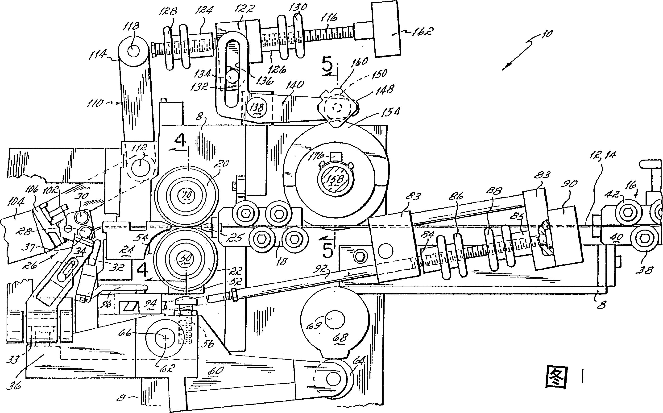
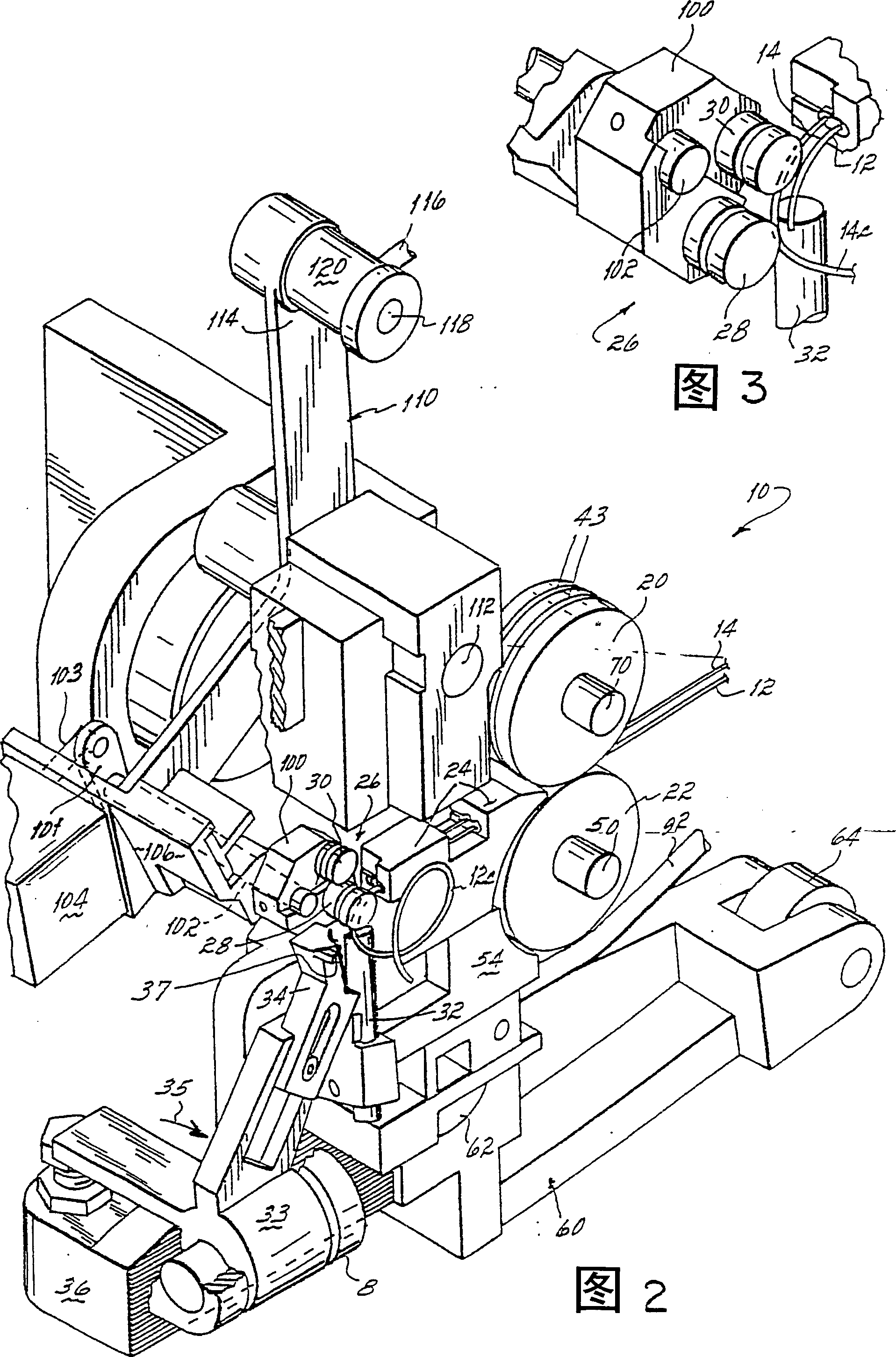
[0017] General composition of spring coiling machine

[0018] The spring coiling machine 10 of the present invention is used to form two steel wires 12 and 14 into spring coils 12c and 14c, respectively. These wires 12 and 14 are preferably of different diameters and are supplied to the spring coiler 10 by two separate wire supply reels (not shown).

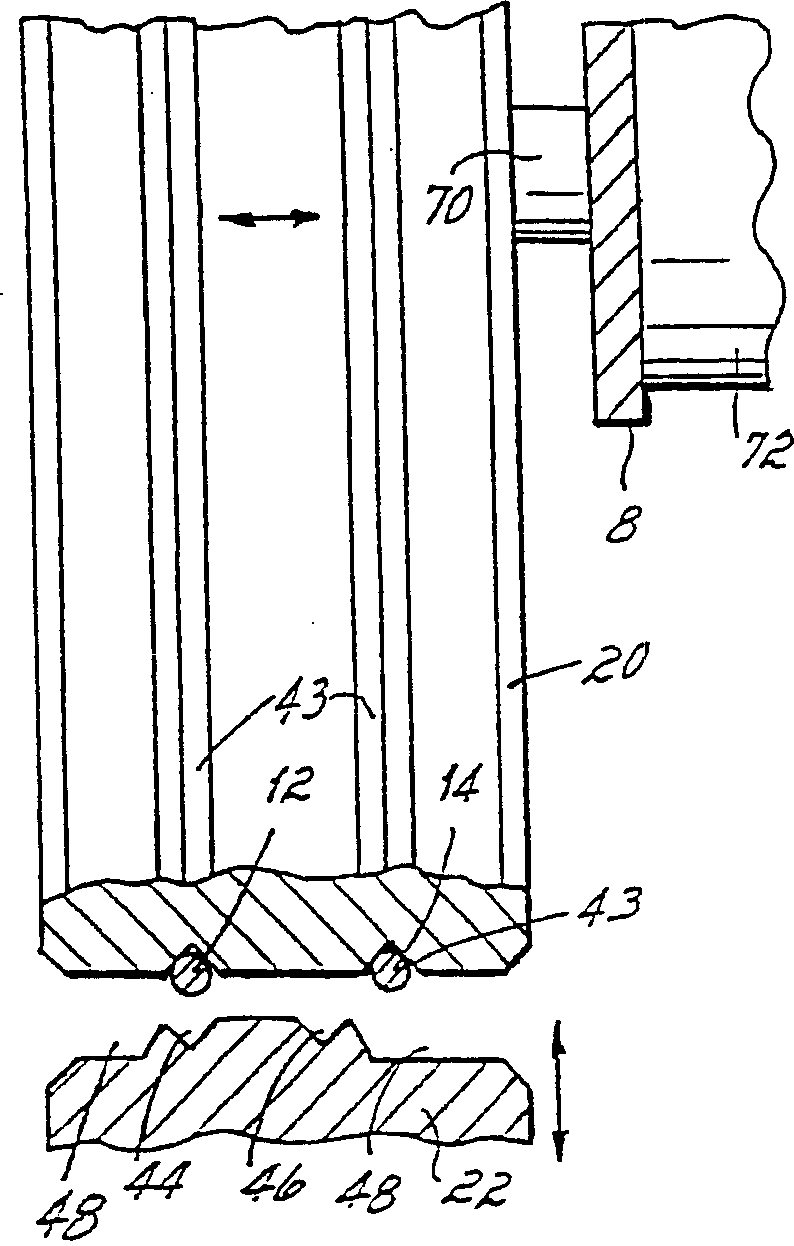
[0019] The spring coiler 10 includes a conventional wire straightener 16 for straightening the wire as it is fed from the supply reel to the machine. After leaving the straightener 16, the wire is fed to a wire guide 18 on the input side of a pair of opposed conveyor rollers 20,22. On the output side of the opposed delivery rollers 20 , 22 there is a wire guide 24 for supplying and guiding wire to a wire forming station 26 . In this forming station, one or the other of the two wires is engaged with one or the other of a pair of coil forming rollers 28, 30 and a pitch determining tool 32, as selected. After the wire has been fo...


PUM


Abstract

A method and machine for selectively manufacturing wire springs from two different wires by feeding the wires through a pair of continuously rotatable opposed feed rollers, which rollers are operative to feed only one of the wires at a time into engagement with a coil forming mechanism having a pair of coil forming tools. The tools are selectively positionable for engagement with one or the other of the two wires depending upon which of the two wires is being fed into the coil forming mechanism.

Description

technical field [0001] This application is a continuation-in-part of US Patent Application Serial No. 09 / 582,909, filed September 18, 2000, and entitled "Spring Winding Automatic Machine." This invention relates to the manufacture of springs, and more particularly, to the manufacture of coil springs for mattresses and furniture. Background technique [0002] In the mattress and furniture industry, it is common practice to manufacture mattress springs on so-called coiling machines, from which the mattress springs are sent directly to assembly machines where they are assembled into rows and columns , which are then combined to produce a mattress spring core. Such machines are described, for example, in US Patent Nos. 4,492,298 and 4,111,241. [0003] In recent years, mattresses have been designed using multiple springs of varying hardness throughout the spring core. In some cases, springs of one firmness are used on one side of the mattress and springs of a different firmne...

Claims


Application Information

Patent Timeline
Patent Type & Authority Patents(China)
IPC IPC(8): B21F3/02B21F23/00B21F35/00
CPCB21F3/02B21F23/002B21F35/00
Inventor 斯捷潘·赫斯克布兰科·杜拉斯
Owner L & P PROPERTY MANAGEMENT CO
Why Eureka
Try Eureka